Assembly
Contents
Take the pcb and lead through the pins from above.
This methode seems to be tricky, but in my case it always worked after the second or thrid “take the PCB out, bend the pins a little bitte, put the pcb in again”: 🙂
Important here: Don’t use force!
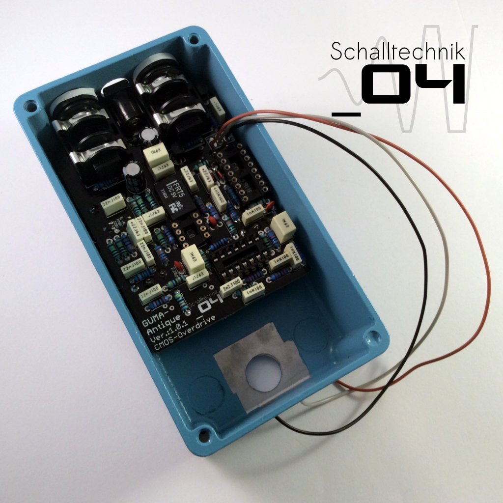 If everything fits, tighten the nuts of the jack and afterwards solder the switches and pots to the pcb then screw the other nuts tight.
ATTENTION: be careful very little space to solder!
Now mount the foot-switch with the teeth washer…
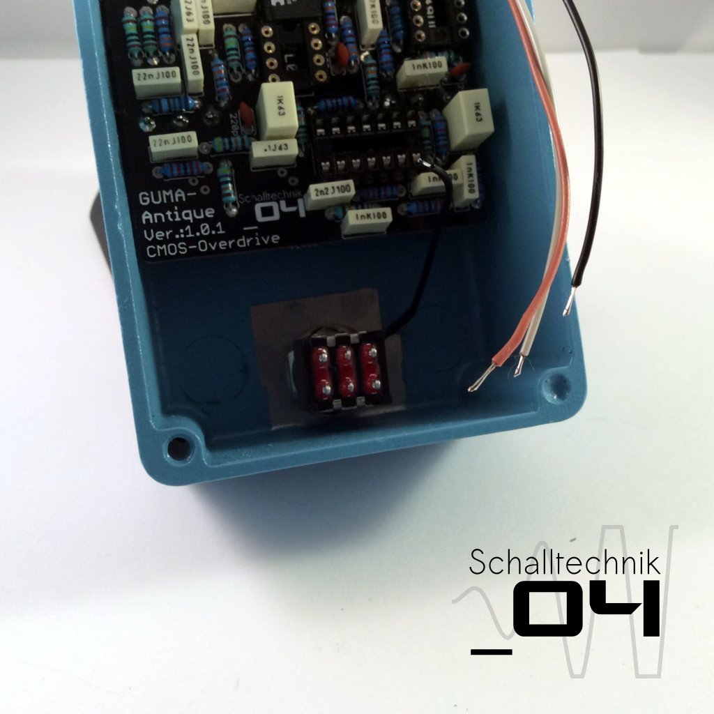
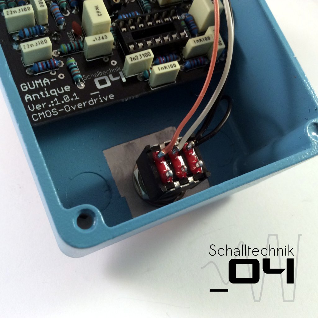
…and solder the cables from the “ON/OFF”-port to the footswitch. The cable vom the teeth washer gets soldered to the same pin as the cable from “ON/OFF”-Port PIN3. (here: black)
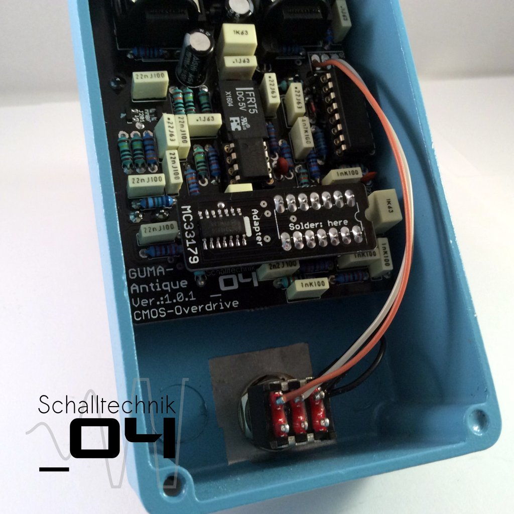 At the very end you can insert theTL072, CD4049 and TL074/MC33179DG. Align correctly!
While inserting the ICs try to stablise the pcb by supporting it with your finger(s) under the pcb.
If you choose to use the MC33179-Adapter, it’s recommended to clue (hot-clue) it to the 1µF capacitor.
That’s it! We’re done. Time for testing! 🙂