PCB-assembly 3/3
Contents
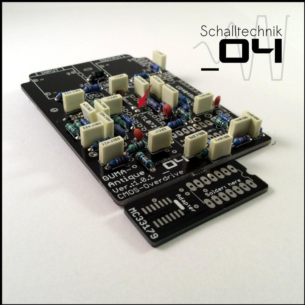
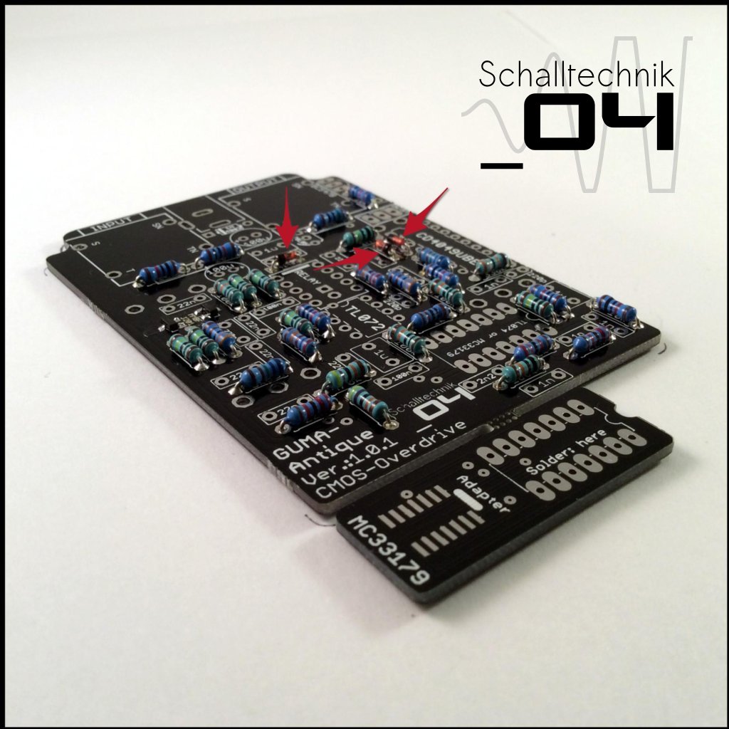 Insert 1N4148 diodes (3x) and solder them. Align correctly!
Sometimes the marking on the silkscreen isn’t very good to see.
Luckily the land has different shapes. The Cathode (the side with marking) comes in the hole with the square land. (see picture above)
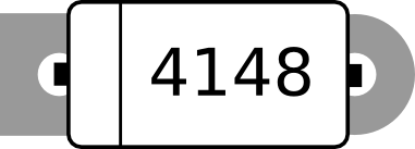
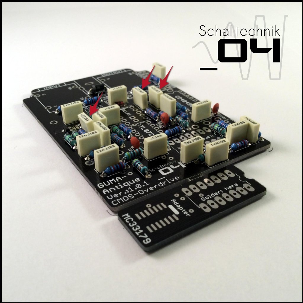
 Insert 1N4003 diode (1x) and solder it. Align correctly!
 Insert 220p capacitors (3x) and solder them.
 Insert 1nF capacitors (4x) and solder them.
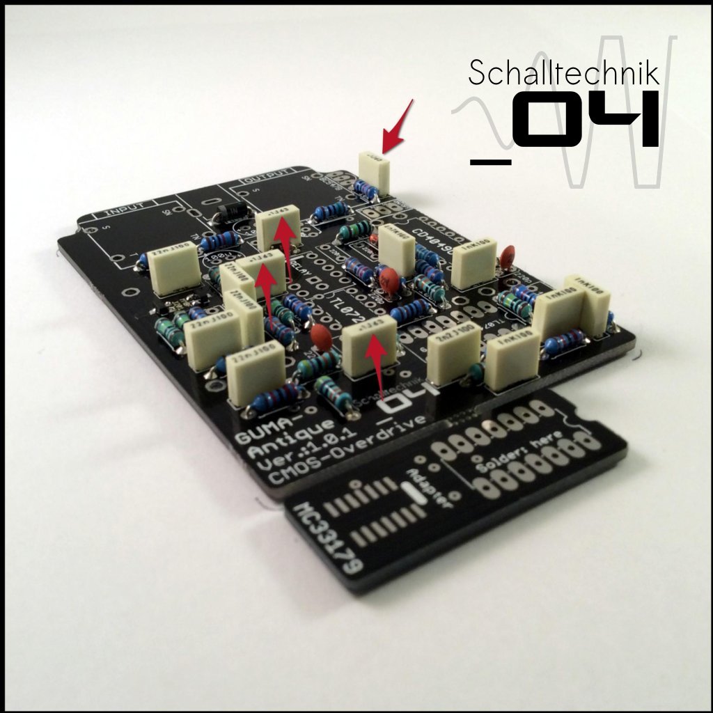
 Insert 2,2nF capacitor (1x) and solder it.
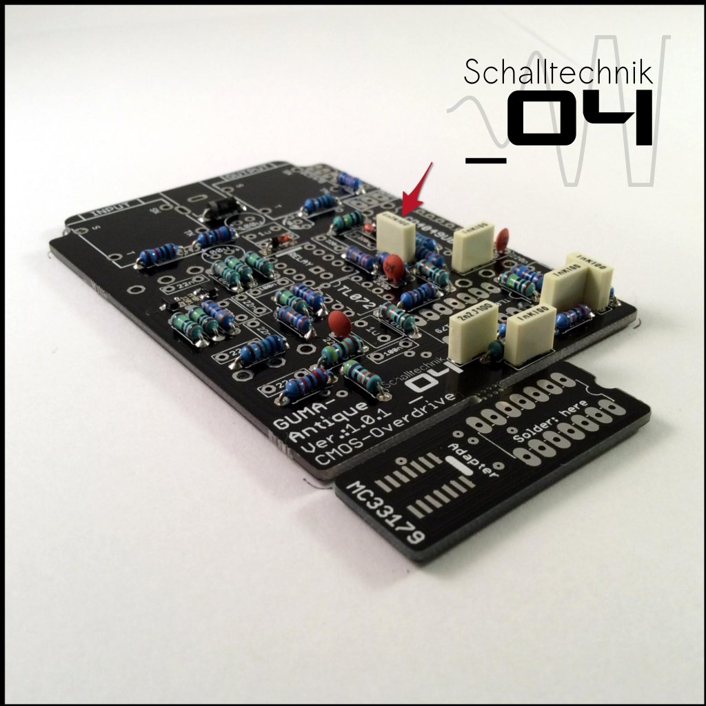 Insert 4,7nF capacitor (1x) and solder it.
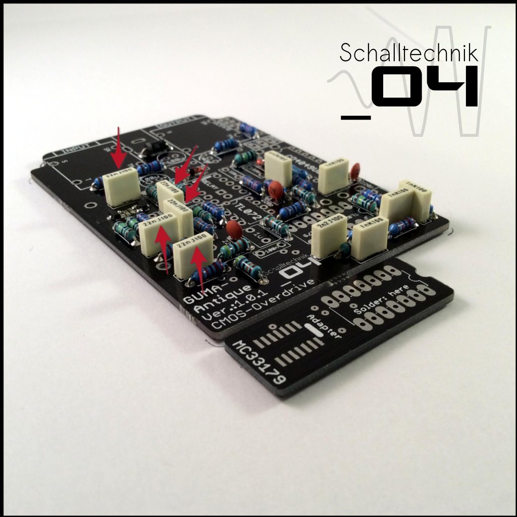 Insert 22nF capacitors (5x) and solder them.
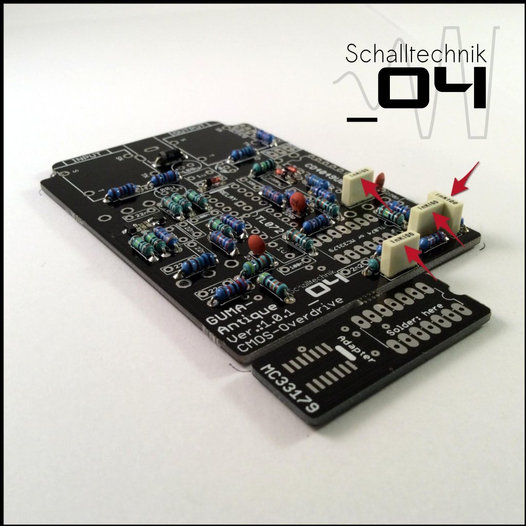
 Insert 100nF (.1) capacitors (4x) and solder them.
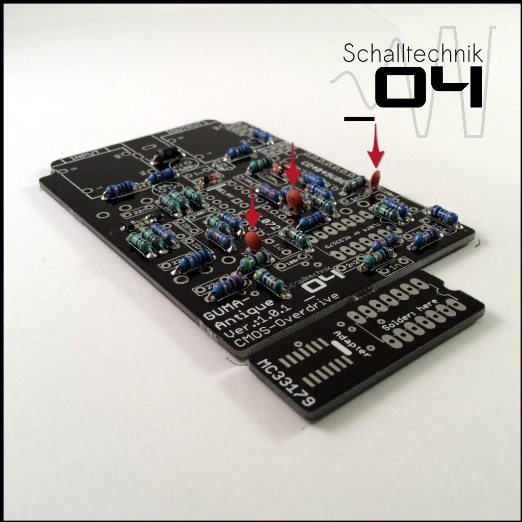
 Insert 220nF (.22) capacitors (3x) and solder them.
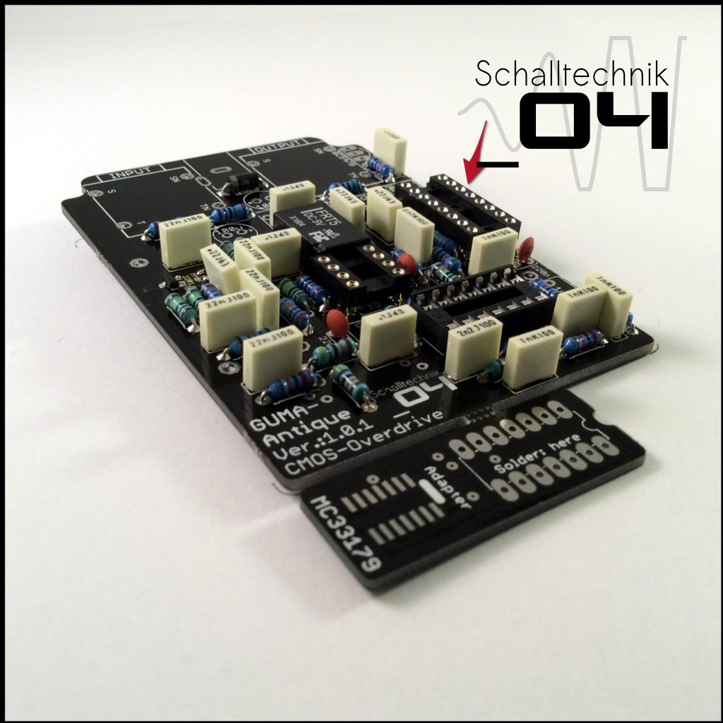
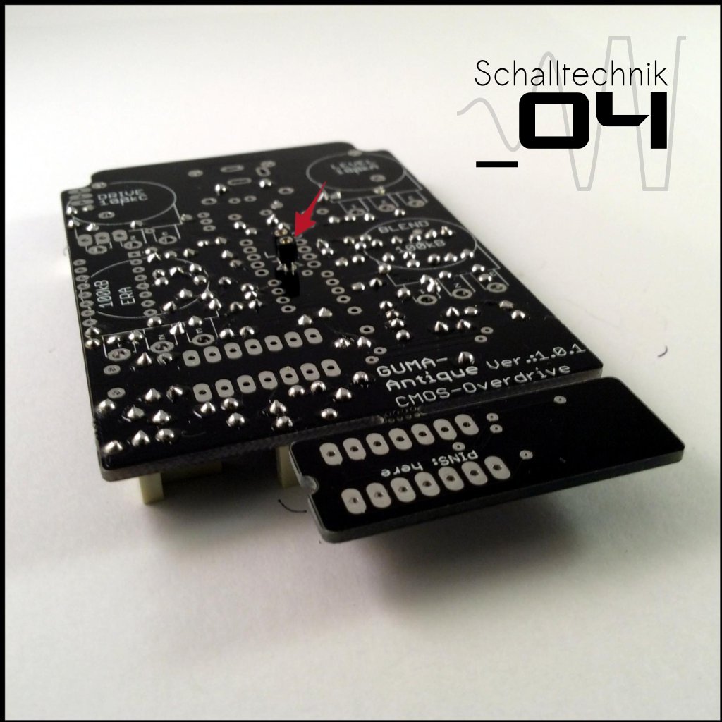 Solder in a socket for the LED. (Reason: next we will solder a relay on the other side of the pcb)
 The pins of the socket have to get cut as plain as possible.
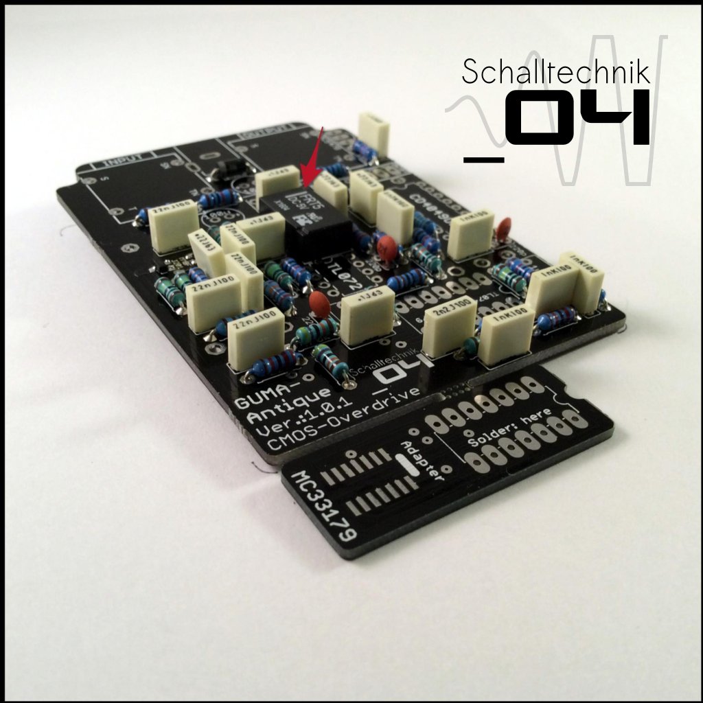 Insert Relay (1x) and solder it. Align correctly! “bar to bar”
Note: Please check if you got the correct relay. The right types are: FRT5 DC5V, Takamisawa A-5W-K or Zettler AZ850-5!
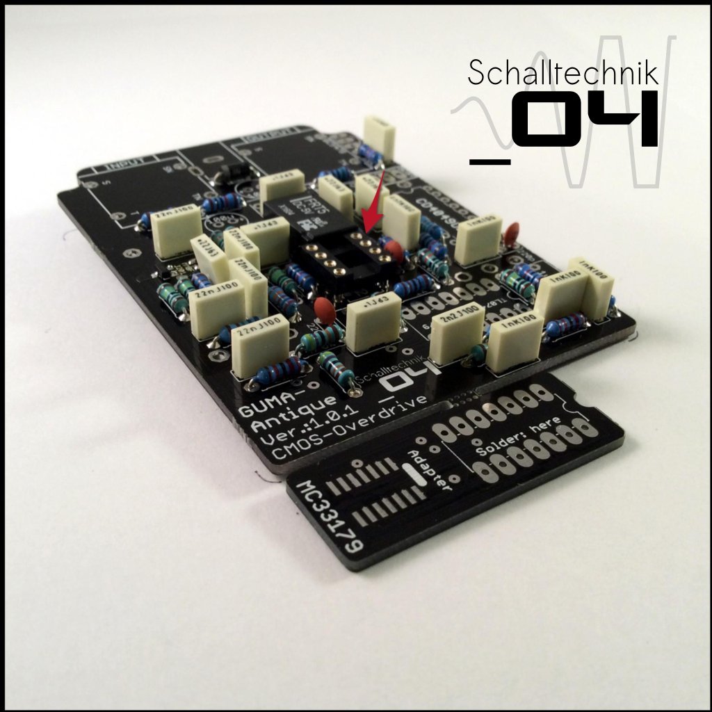 Insert 8-Pin DIL-Socket (1x) and solder it. Align correctly!
 Insert 14-Pin DIL-Socket (1x) and solder it. Align correctly!
 Insert 16-Pin DIL-Socket (1x) and solder it. Align correctly!
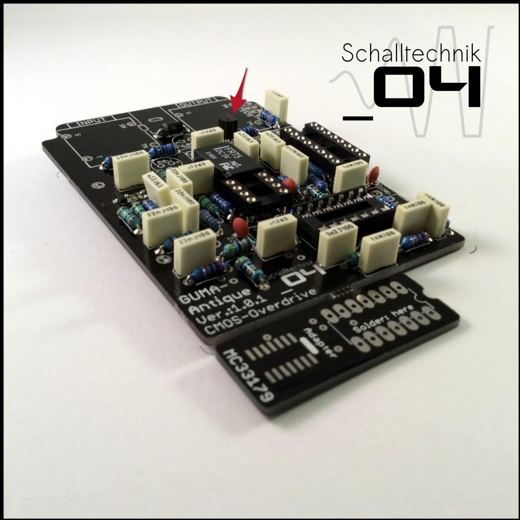 Insert 78L05 (1x) and solder it. Align correctly!
 Insert BC547B (1x) and solder it. Align correctly!
 Insert 1µF capacitors (3x) and solder them.
If you choose to use the MC33179-Adapter, it’s recommended to install the 1µF left to the socket laying.
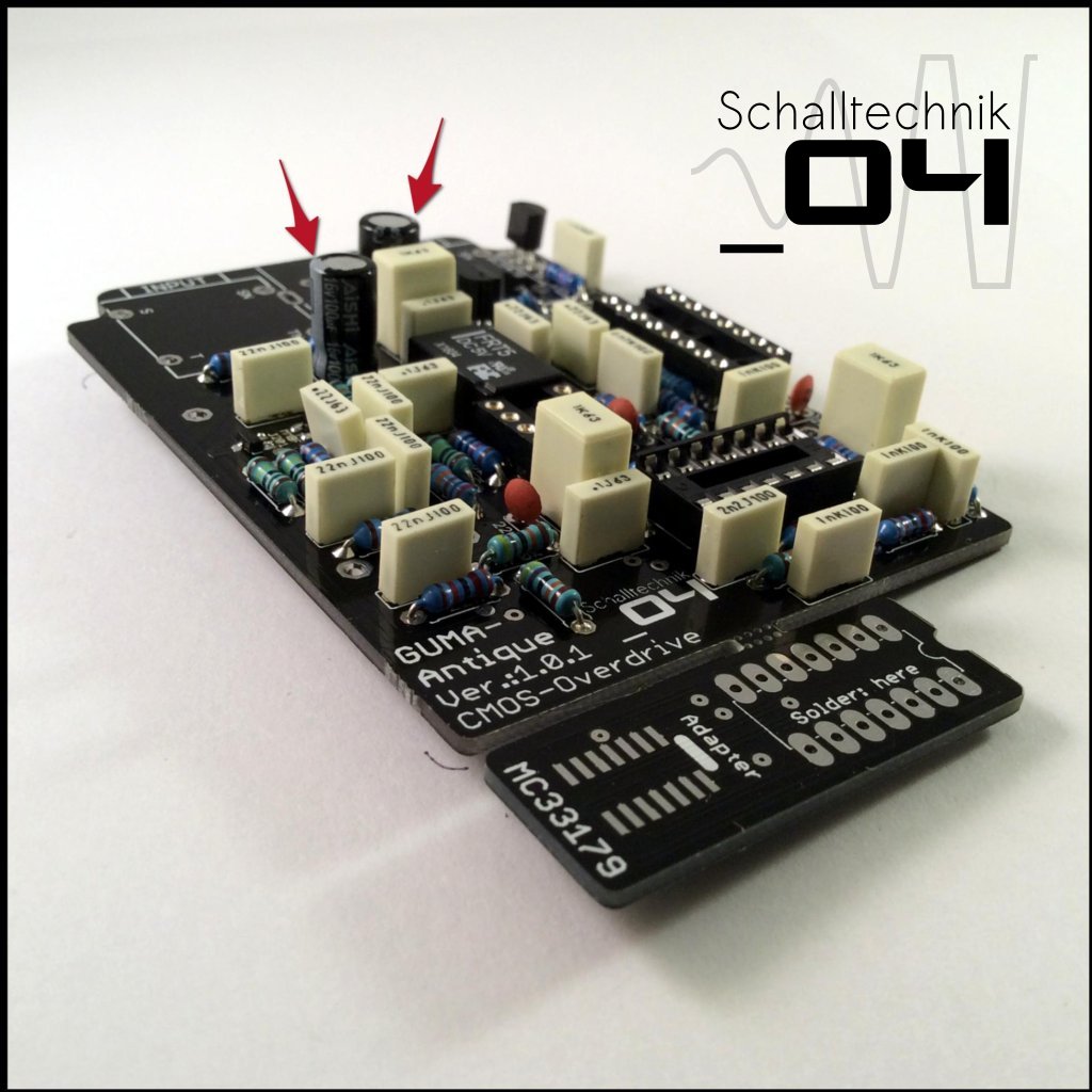 Insert 100µF capacitors (2x) and solder them. Align correctly!