Assembly
Contents
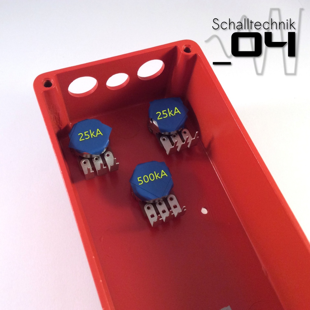 Screw the pots in the enclosure. Put two layers of tape on the pots to ensure the housing can’t touch the soldered points.
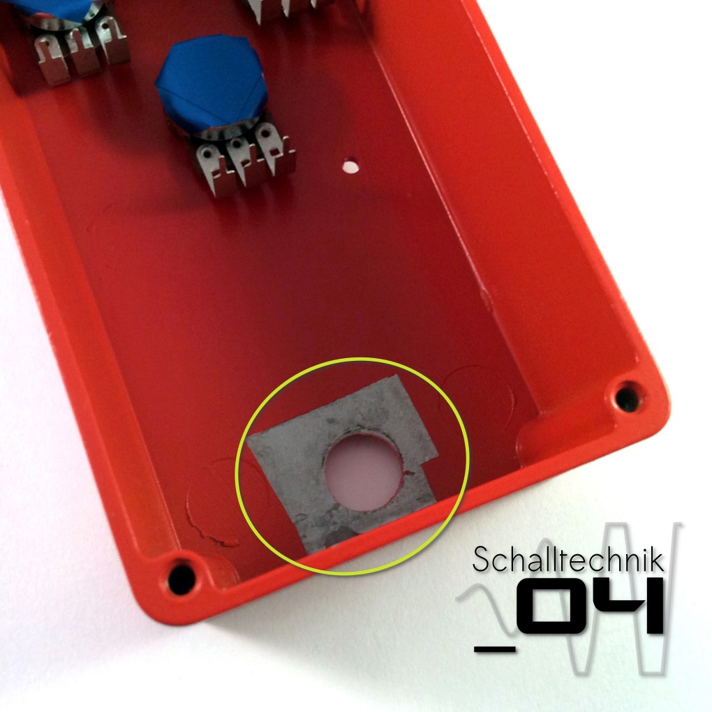 Now we remove the tape we’ve put on before painting.
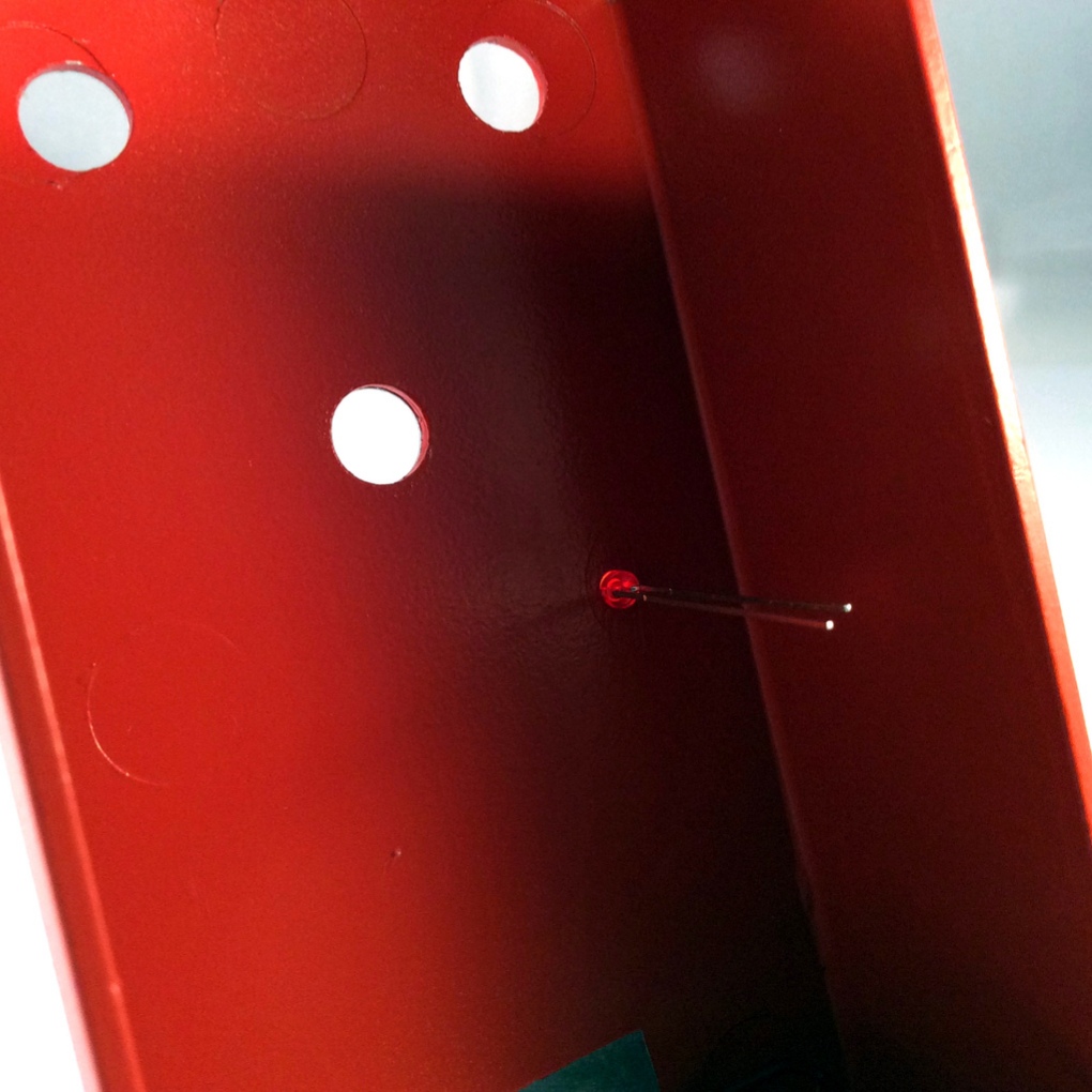 Insert the led into the enclosure.

The anode (+) has to be on the left side.
Take the pcb and lead through the pins from above.
This methode seems to be tricky, but in my case it always worked after the second or thrid “take the PCB out, bend the pins a little bitte, put the pcb in again”: ?
Important here: Don’t use force!

 If everything fits, tighten the nuts of the jacks…

 and afterwards solder the pots and the led to the pcb.
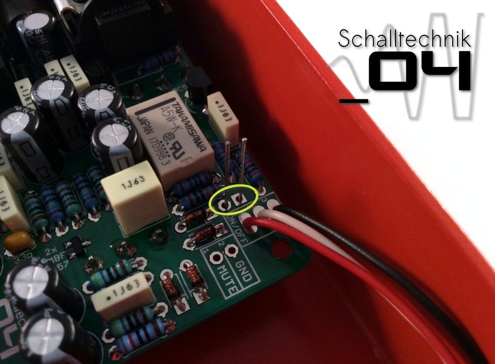
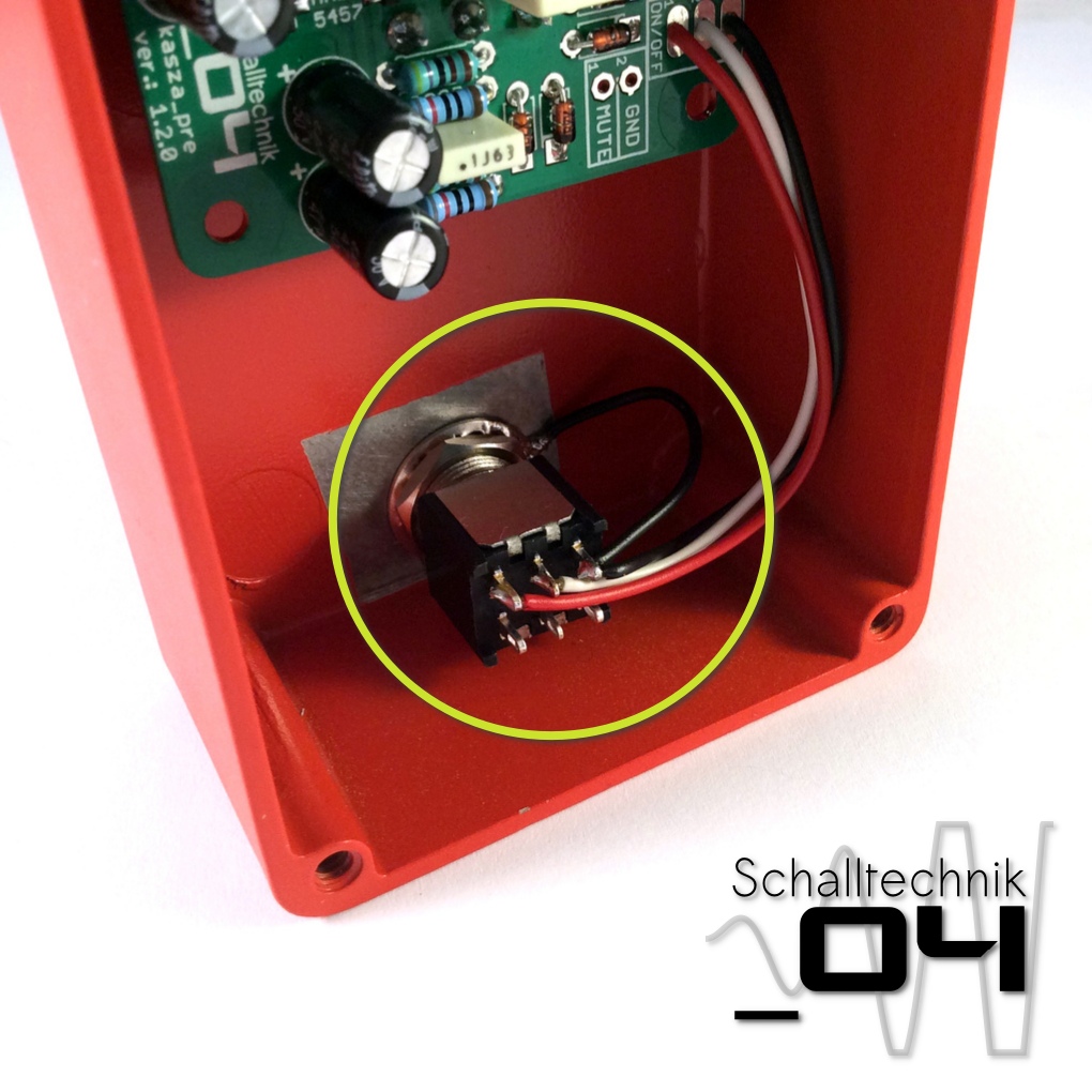 Now mount the foot-switch with the teeth washer and solder the cables from the “ON/OFF”-port to the footswitch. The cable vom the teeth washer gets soldered to the same pin as the cable from “ON/OFF”-Port PIN3. (here: black)
 Finally screw the other nuts tight.
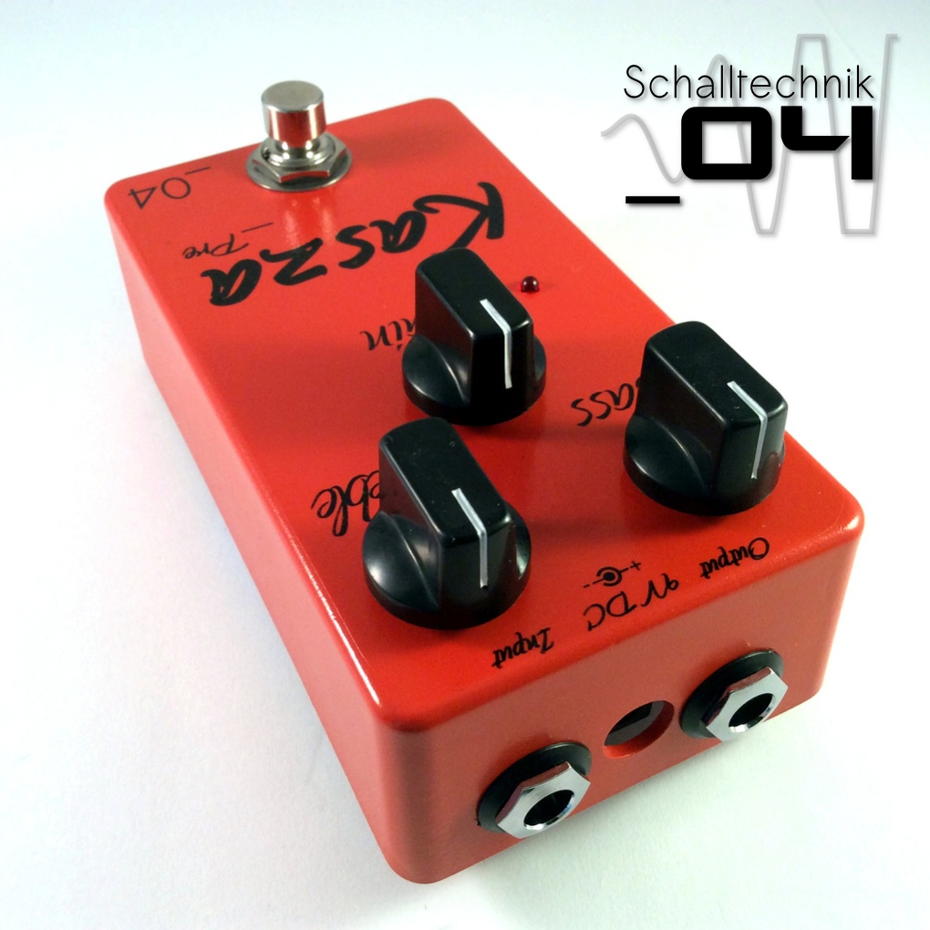
That’s it! We’re done. Time for testing! ?