Assembly
Contents
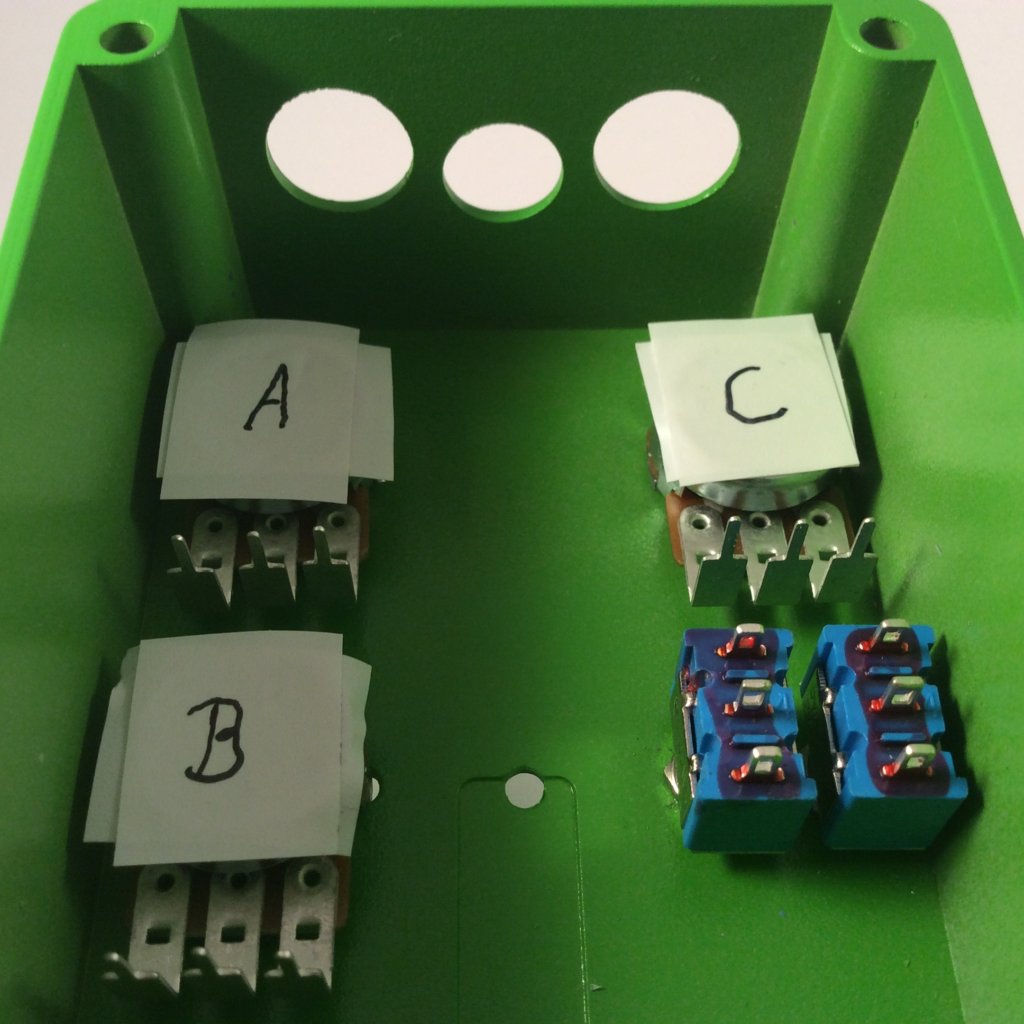
Screw the pots and switches in the enclosure. Put two layers of tape on the pots to ensure the housing can’t touch the soldered points.
Note: The letters correspont to the characteristic of the pots: 1x100kA (log), 1x100kB (lin) und 1x100kC (rev log).
Note2: For new kits pots with dust cover are used. The 100kC (rev log)-types weren’t available with dust-cap. Although the pots are from the same brand the nuts differ a bit. So keep them in order.
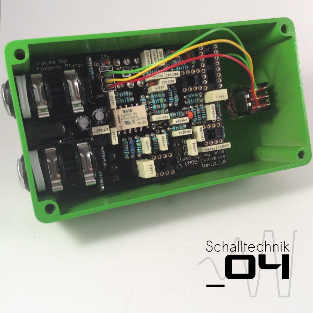
Take the pcb and lead through the pins from above.
This methode seems to be tricky, but in my case it always worked after the second or thrid “take the PCB out, bend the pins a little bitte, put the pcb in again”: 🙂
Important here: Don’t use force!
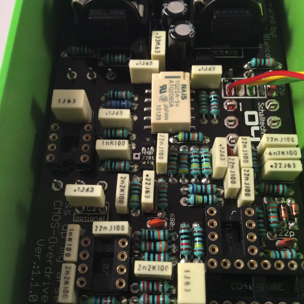
If everything fits, tighten the nuts of the jack and afterwards solder the switches and pots to the pcb then screw the other nuts tight.
Now mount the footswitch with the teeth washer…
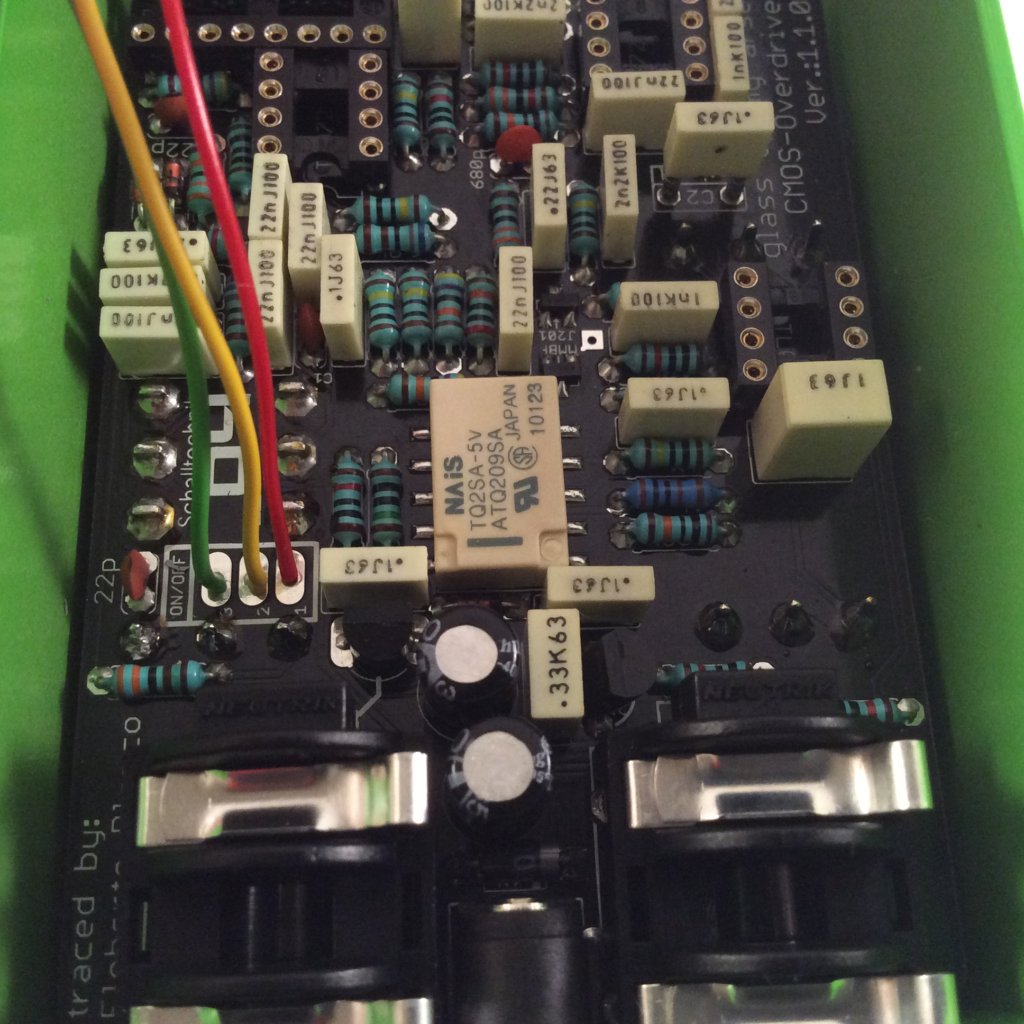
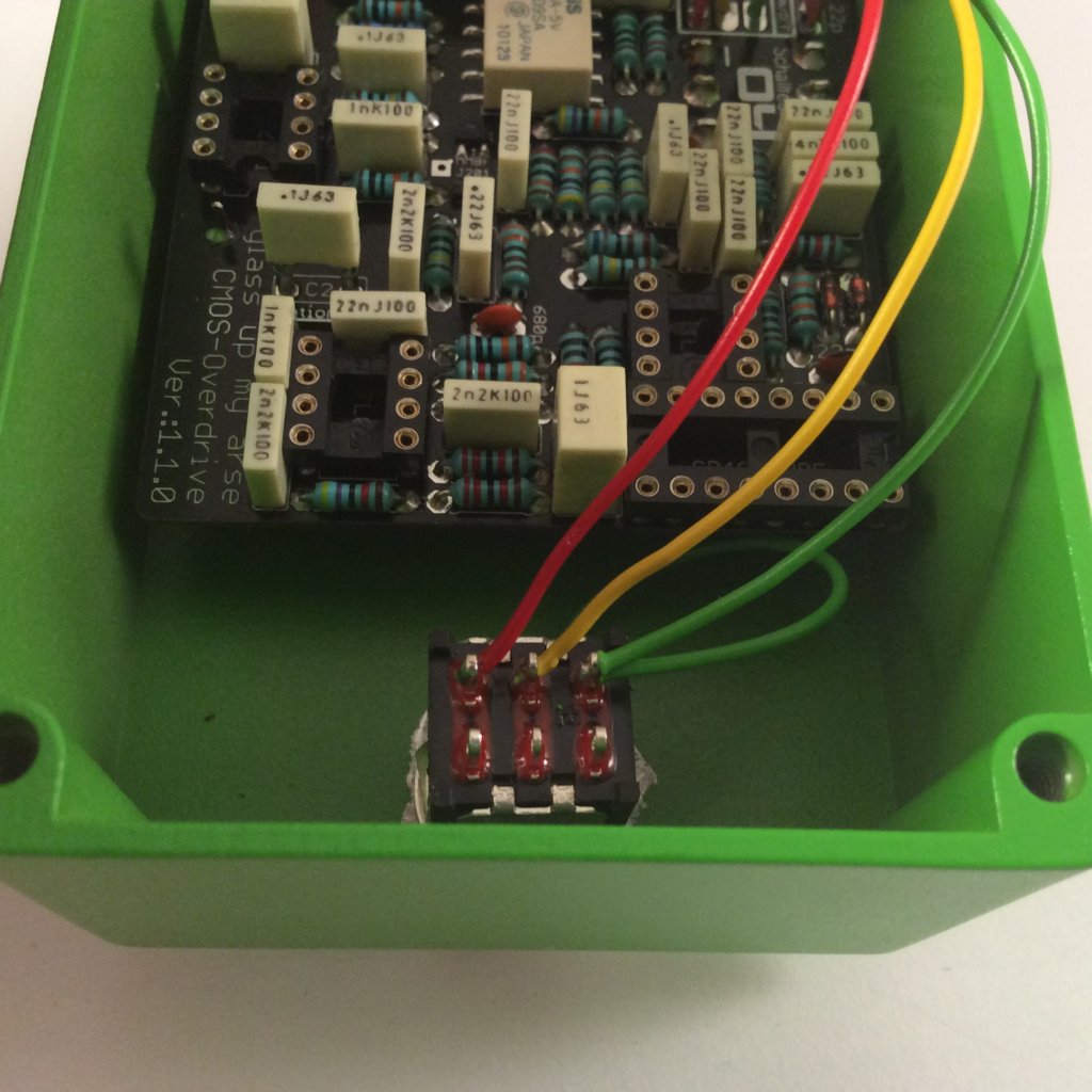 …and solder the cables from the “ON/OFF”-port to the footswitch. The cable vom the teeth washer gets soldered to the same pin as the cable from “ON/OFF”-Port PIN3. (here: green)
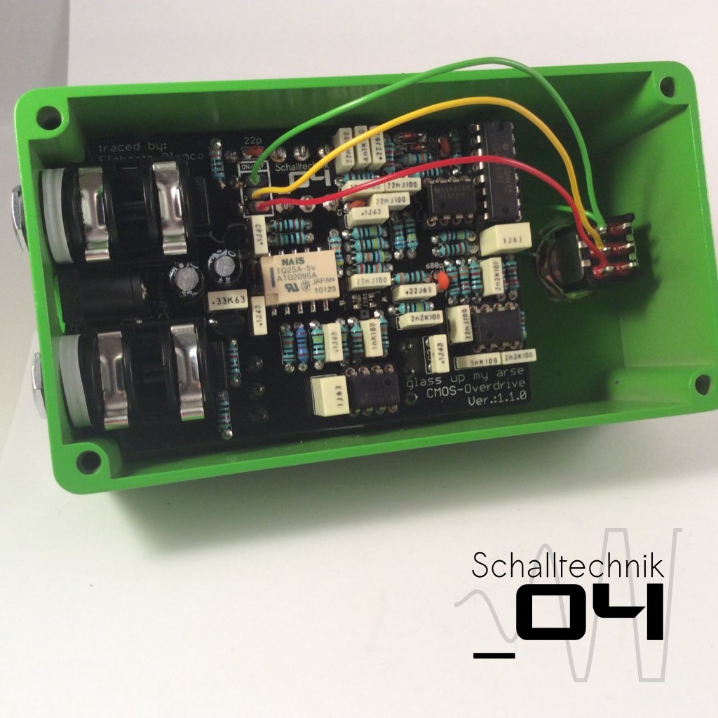 At the very end you can insert the three OPAs (TL072) and the CMOS Hex-Inverter (CB4049). Align correctly!
While inserting the ICs try to stablise the pcb by supporting it with your finger(s) under the pcb.
That’s it! We’re done. Time for testing! 🙂