PCB-assembly 3/3
Contents
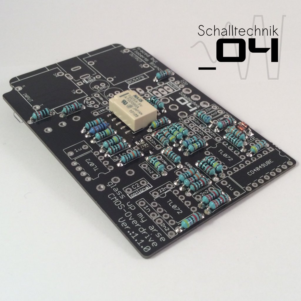
Insert 1N4148 diodes (3x) and solder them. Align correctly!
Sometimes the marking on the silkscreen isn’t very good to see.
Luckily the land has different shapes. The Cathode (the side with marking) comes in the hole with the square land. (see picture above)
 Insert 1N4003 diode (1x) and solder it. Align correctly!
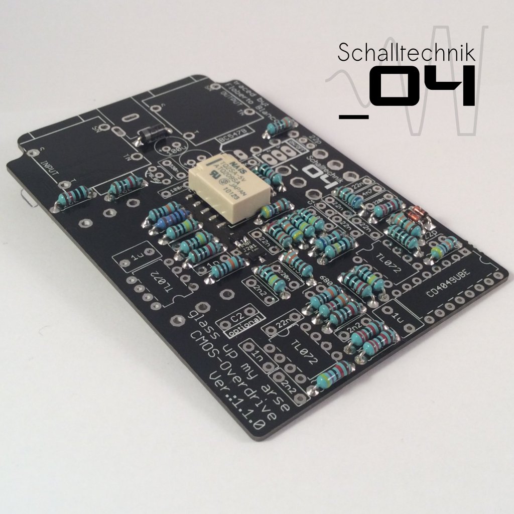
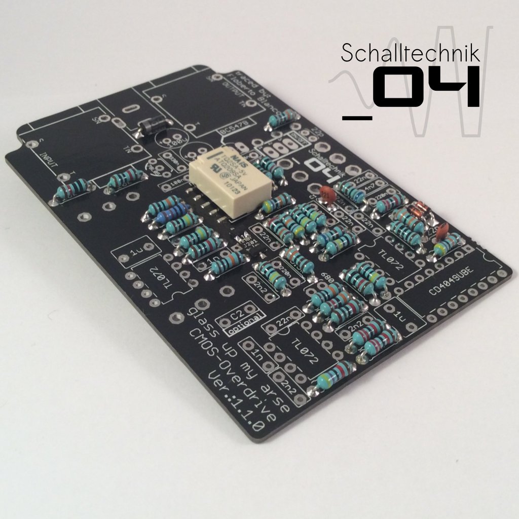
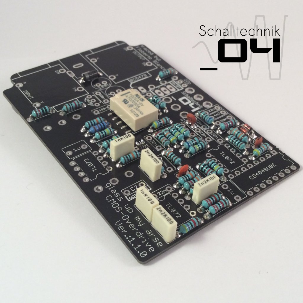
Insert 22p capacitors (2x) and solder them.
Note: In this picture I forget one 22p cap. The missing one next to the “ON/OFF”-Port
 Now we need to make a decision:
C1 has no value given, because we can put two different values in that place.
the following values are available:
- 220pF (standard)
- 470pF (mod)
C1 is responsible for the behavior of the attack-switch.
Boost:
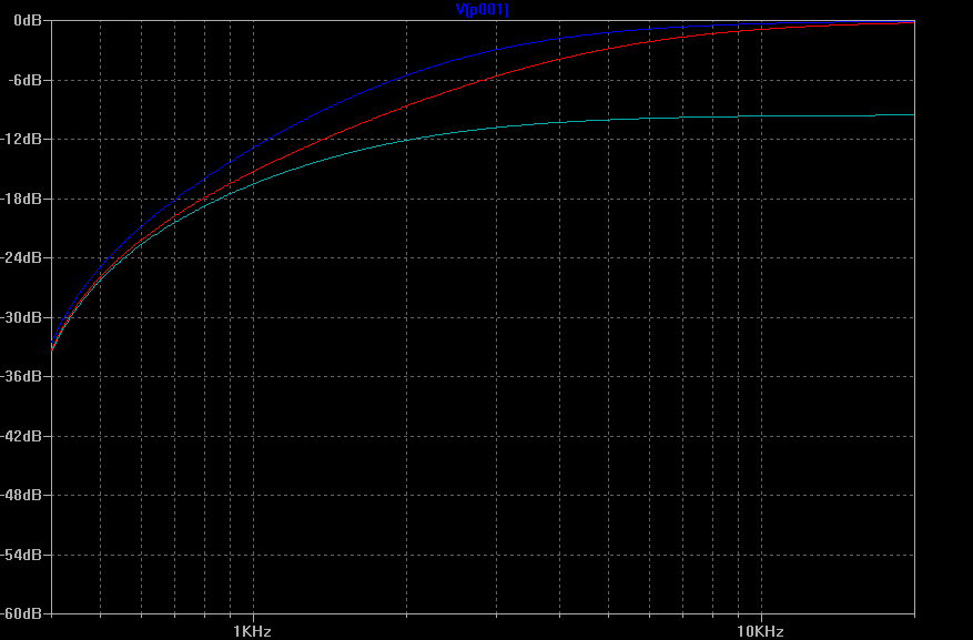
- blue: 470pF
- red: 220pF
- aqua: FLAT (as reference)
Cut:
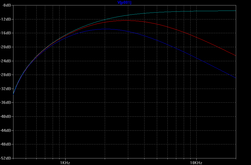
- blue: 470pF
- red: 220pF
- aqua: FLAT (as reference)
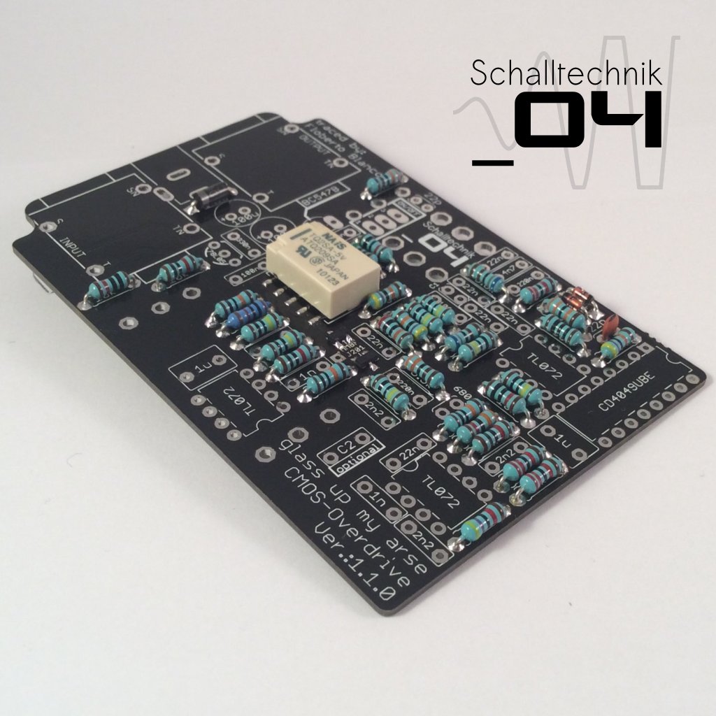
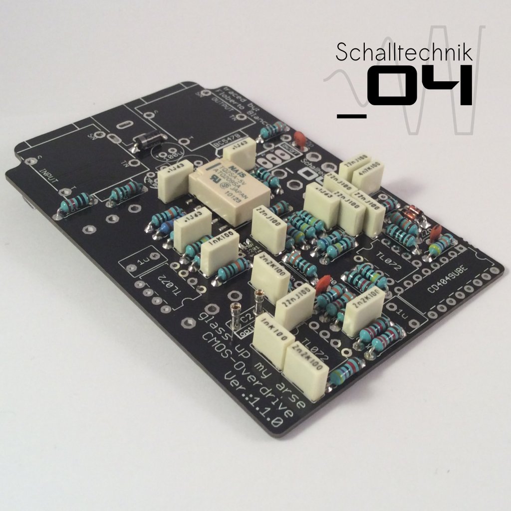
 Insert 680pF capacitor (1x) AND 1nF capacitors (2x) and solder them.
 Insert 2,2nF capacitors (3x) and solder them.
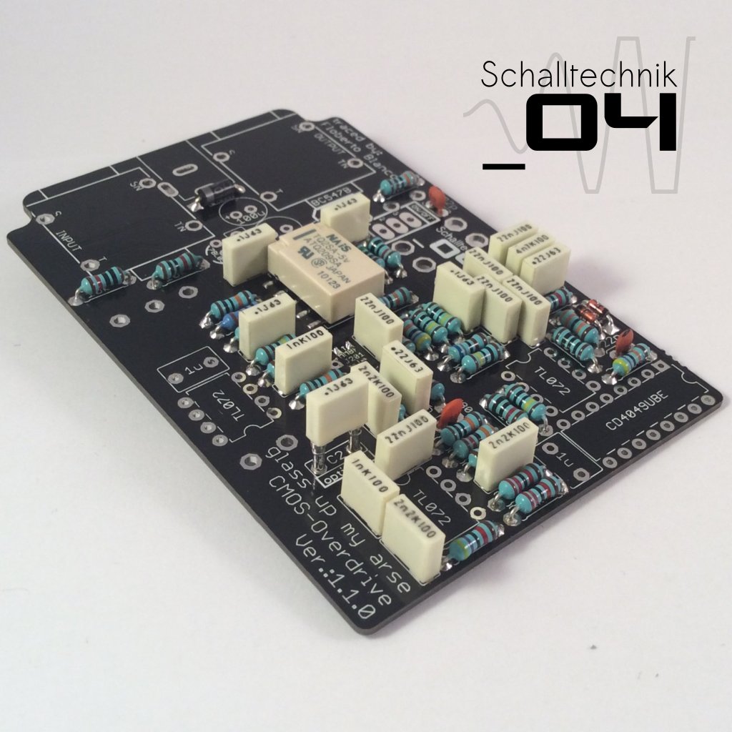
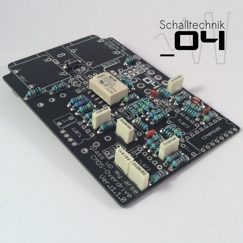 Insert 4,7nF capacitor (1x) and solder it.
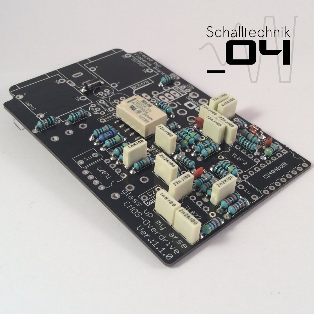 Insert 22nF capacitors (6x) and solder them.
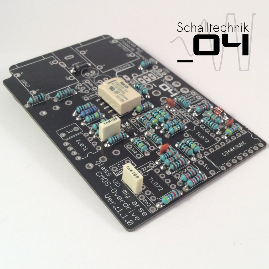
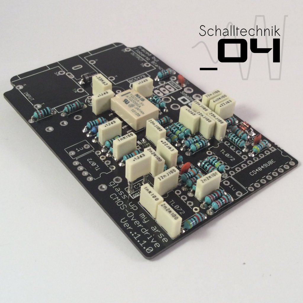
 Insert 100nF (.1) capacitors (4x) and solder them.
 C2 is an optional capacitor. If you like you can put socket there to be flexible. You can add in a 100nF (.1u) capacitor. When added the Overdrive reacts more clear at high gain setting. Test it! It’s very subtle.
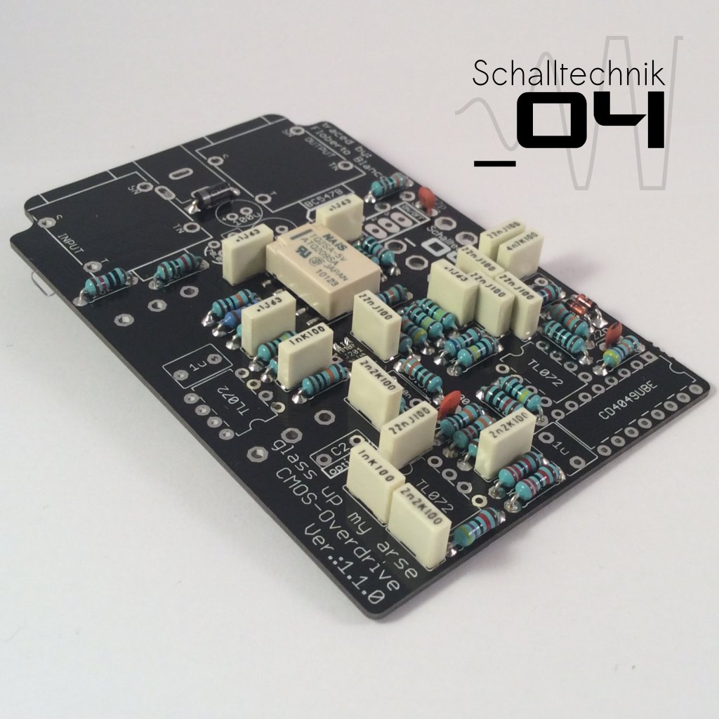
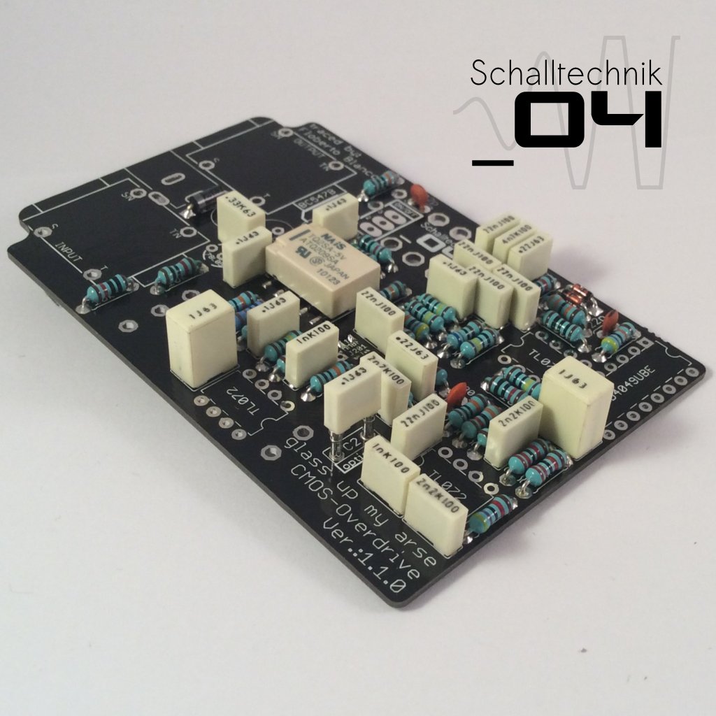
 Insert 220nF (.22) capacitors (2x) and solder them.
 Insert 330nF capacitor (1x) and solder it.
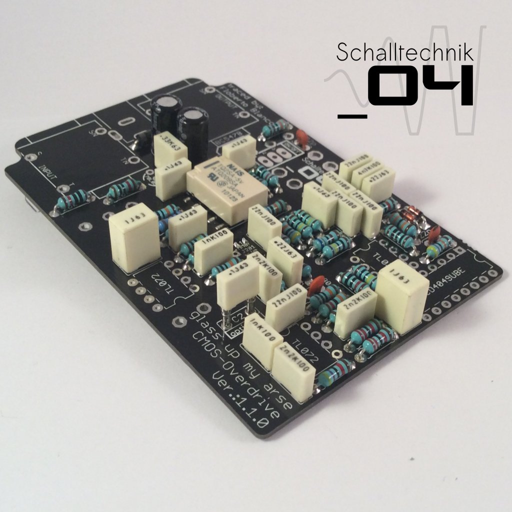
 Insert 1µF capacitors (2x) and solder them.
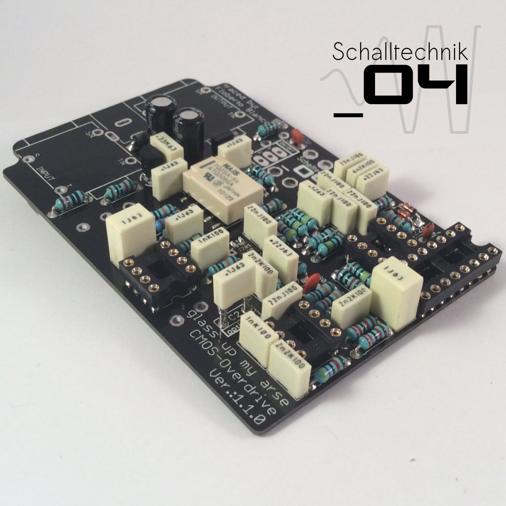
 Insert 100µF capacitors (2x) and solder them. Align correctly!
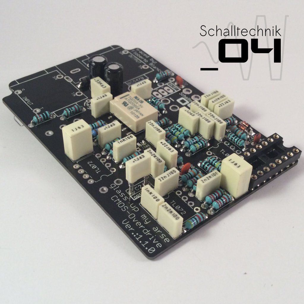 Insert 16-Pin DIL-Socket (1x) and solder it. Align correctly!
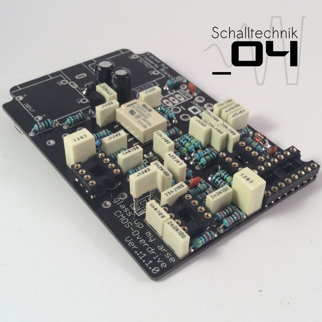
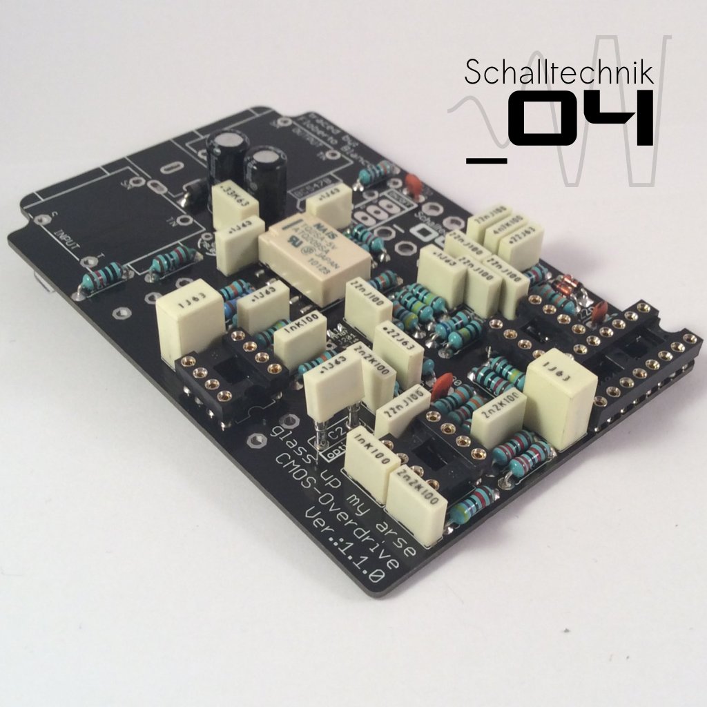 Insert 8-Pin DIL-Sockets (3x) and solder them. Align correctly!
 Insert 78L05 (1x) and solder it. Align correctly!
 Insert BC547B (1x) and solder it. Align correctly!