PCB-assembly 1/3
Contents
HALT! STOP!
Are you starting to assemble a kit bought not directly from schalltechnik_04.de? If yes, check every part again the list of parts.
Really! E.V.E.R.Y. Part!
If anything is wrong -> contact your seller!
If you’re not certain, if it is the correct part -> contact us.
It’s 10 mins invested, that will later safe you headaches.
HALT! STOP!
With that out of the way, let’s start building. 🙂
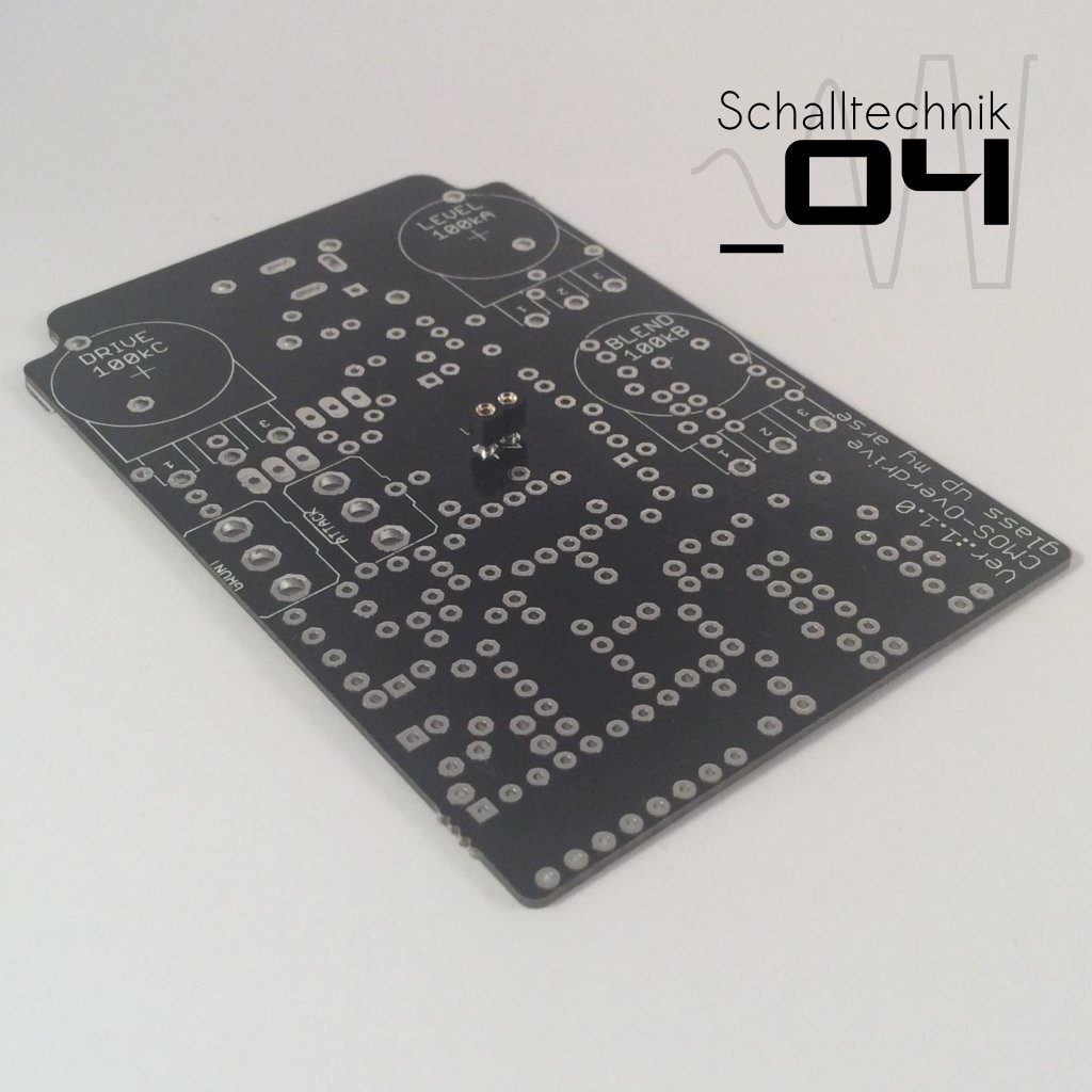
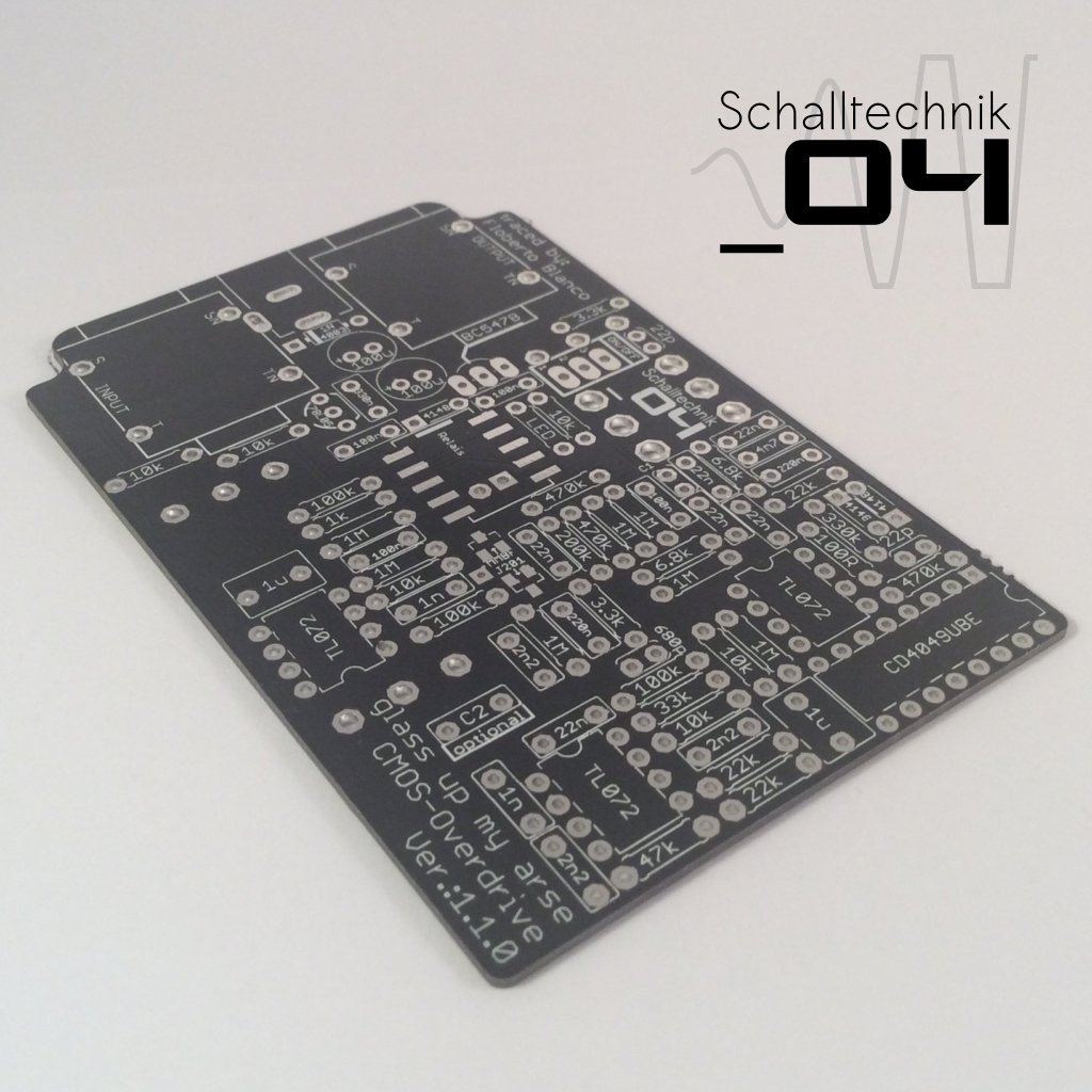 First we start with the pcb.
 On the picture above you see the first step for soldering the JFETs (MMBF-J201). One pad per JFET gets coated with solder. Now you take a JFET with tweezers and place and fix it on the corresponding place. Heat up the pad (you coated before) and pin (of the JFET) to get a joint.
ATTENTION: JETs are very sensitive for heat and ESD. This step is the most crucial step in the whole instruction. Take care and take your time.
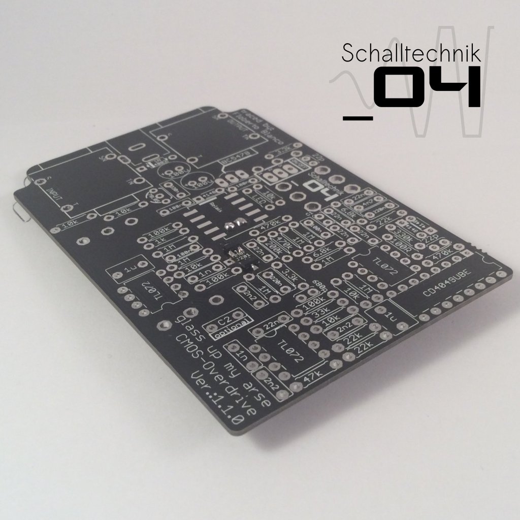
 The other pins of the JFETs can be soldered normally (heat up the pad, put solder to it, done).
 Solder in a socket for the LED. (Reason: next we will solder a relay on the other side of the pcb)
 The pins of the socket have to get cut as plain as possible.
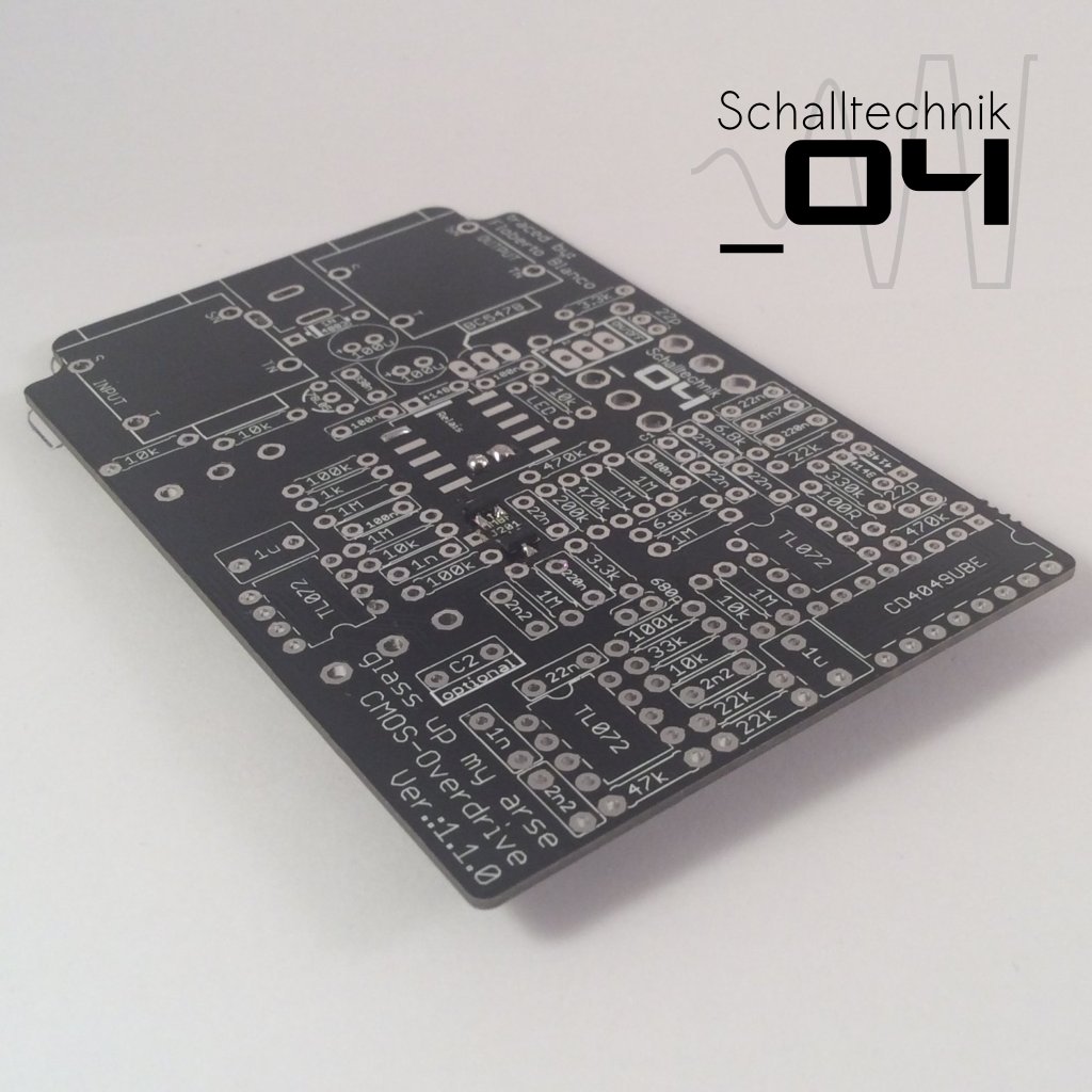 Now we do the same procedure as with the JFETs: Coat one pad on the pcb…
NOTE: Newer versions (≥ 1.2.0) of the pcb use a through hole Relay. It’s easier to solder.
Note: Please check if you got the correct through hole relay. The correct types are: FRT5 DC5V, Takamisawa A-5W-K or Zettler AZ850-5!
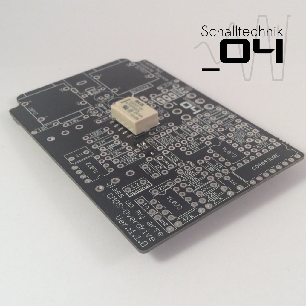 …and take the relay. Put it in the right place und solder the coated pad to the relay pin. Afterwards solder the other 9 pins/pads together.
Align correctly!