Assembly Preparation
Contents
Now we take the tooth washer which comes with the footswitch and solder a wire to it.
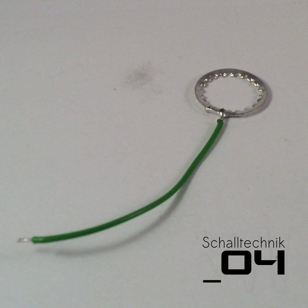 We’ll use the tooth washer later to ground the enclosure.
About shielding:
If we ground the enclosure it will act like a shild. Ungrounded the shielding effect is much smaller.
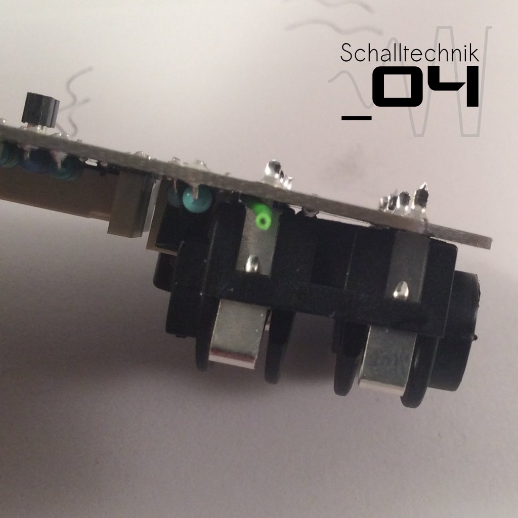
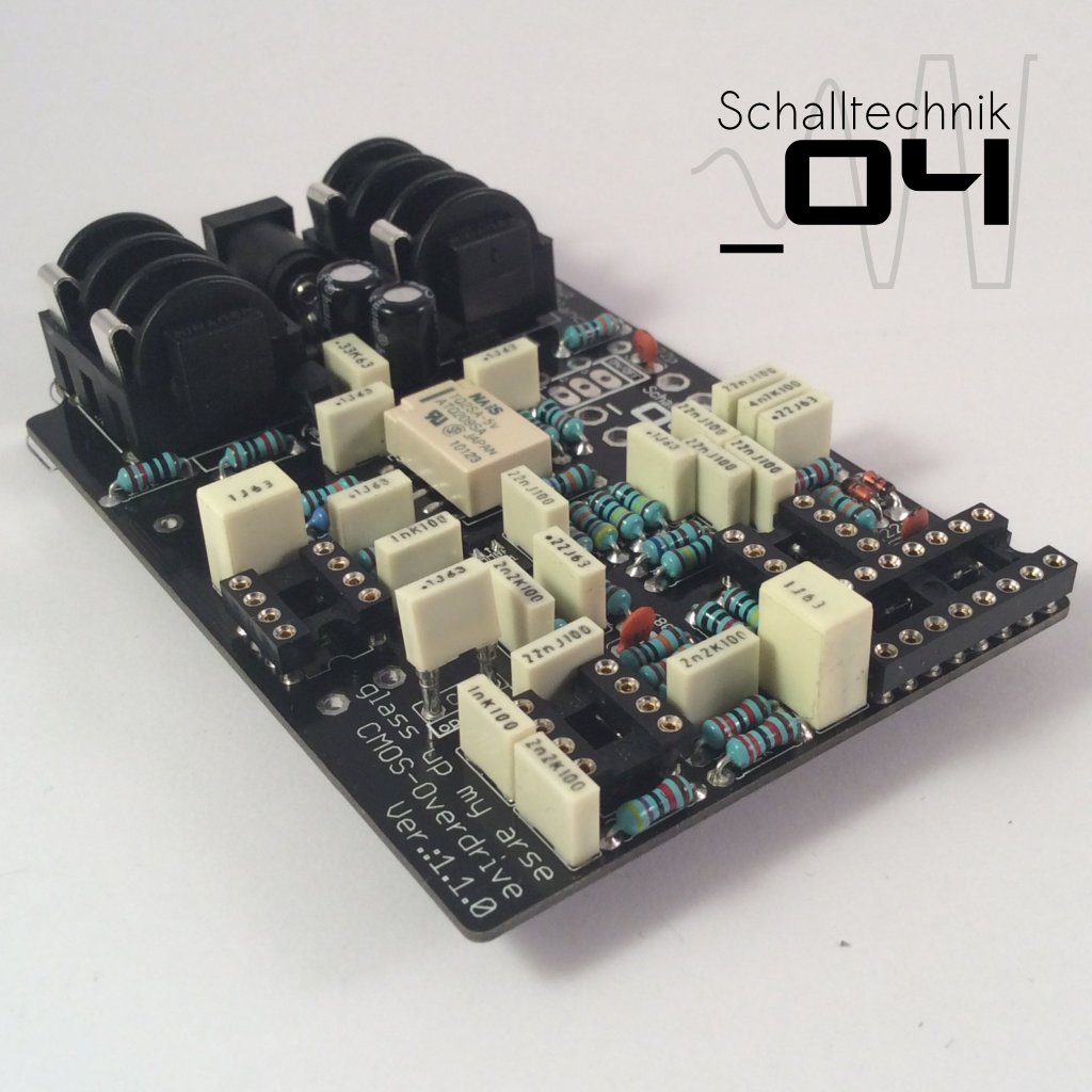
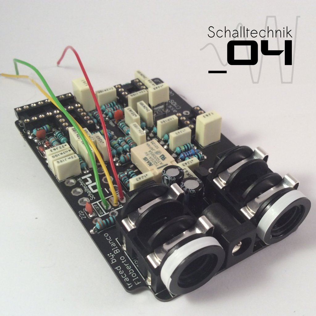
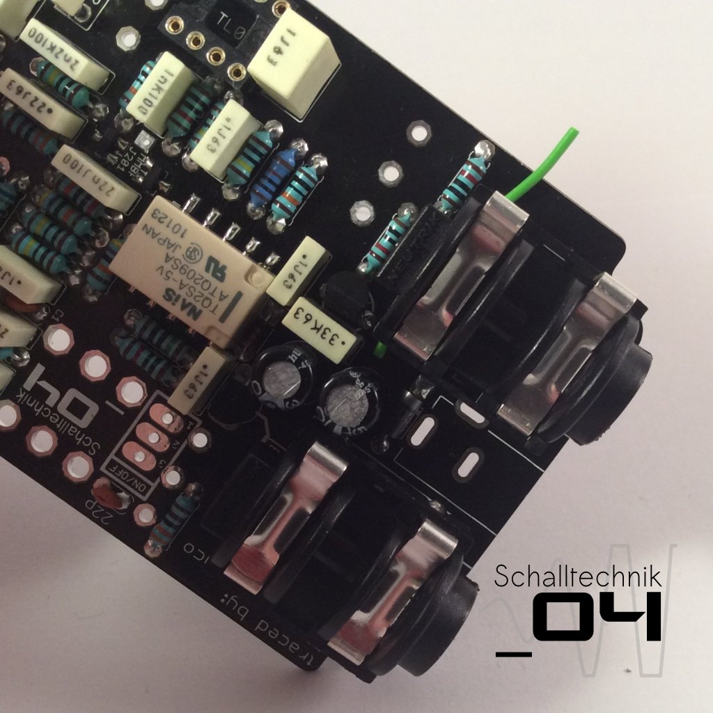 The 125B/1590N1-enclosures aren’t rectangular, thus we need to mount the input- and outputjacks with a small angle. I use a piece of wire, which I put under the jacks (see in the pictures). Then I solder them.
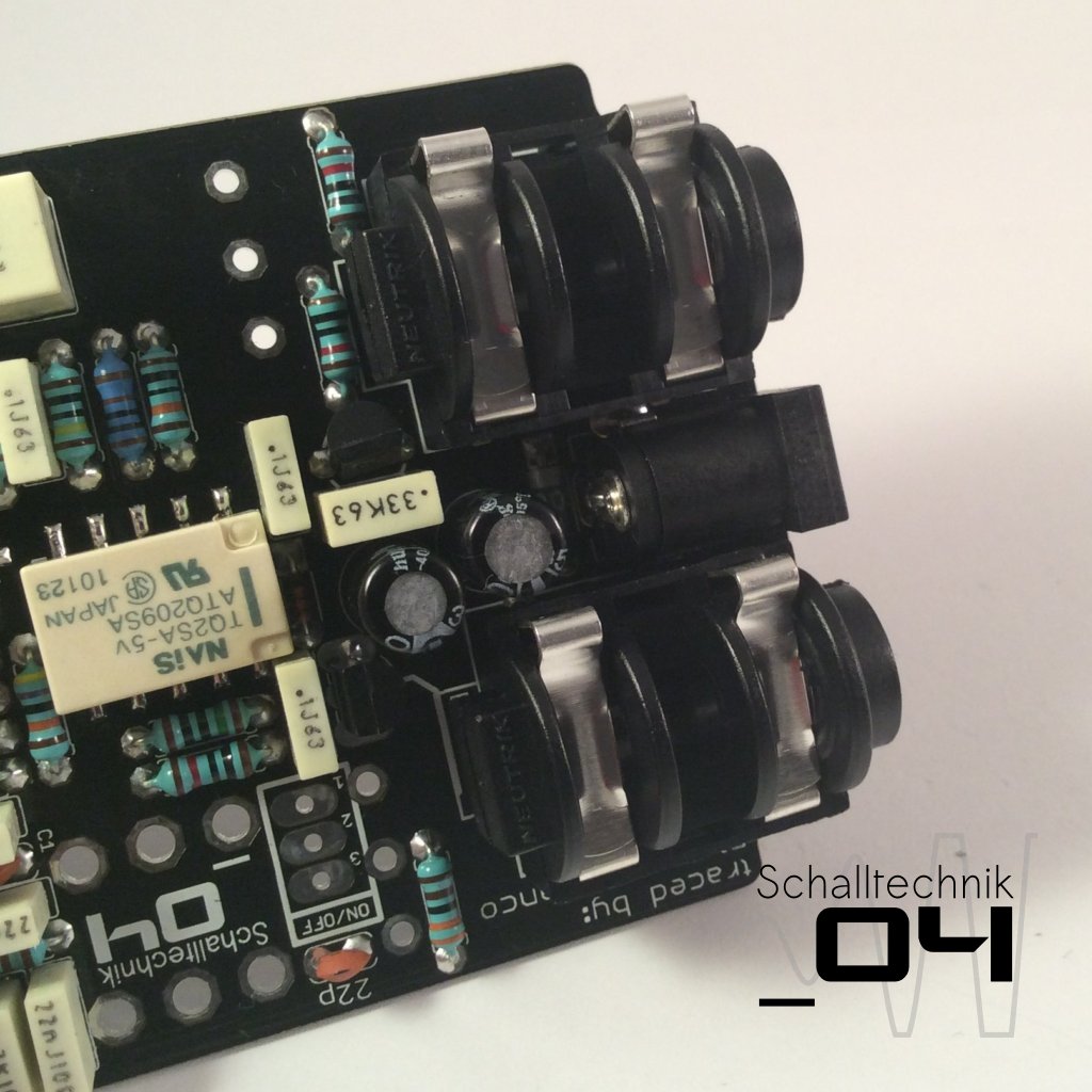 Insert the dc-jack…
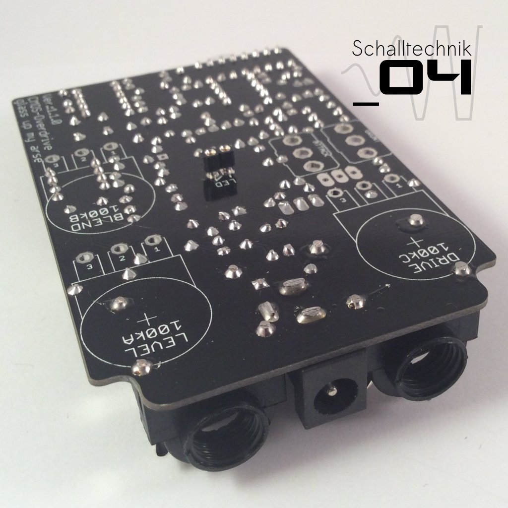 and solder it.
Note: If you like, you can cautiously clean the areas arround the jacks again with PCB-cleaner.
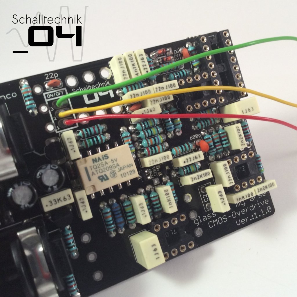
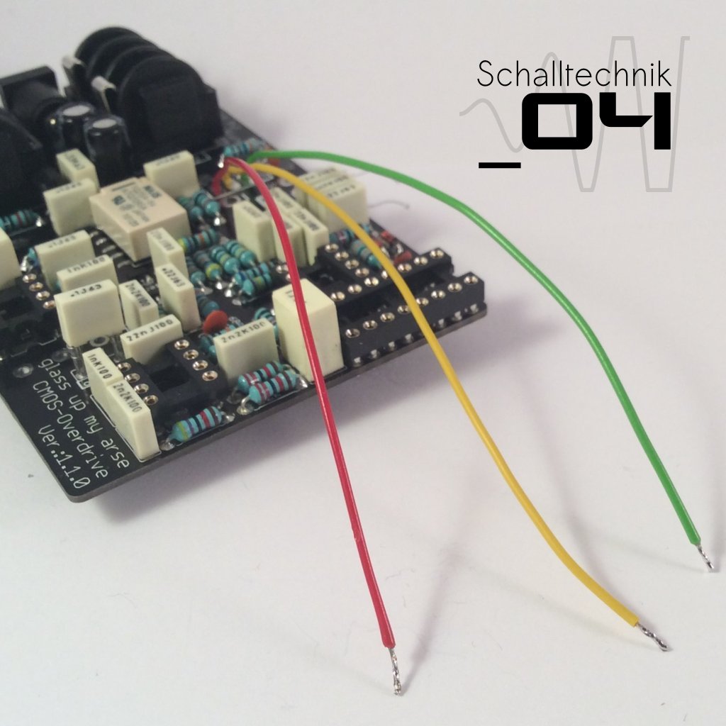 Solder wires to the “ON/OFF”-Port.
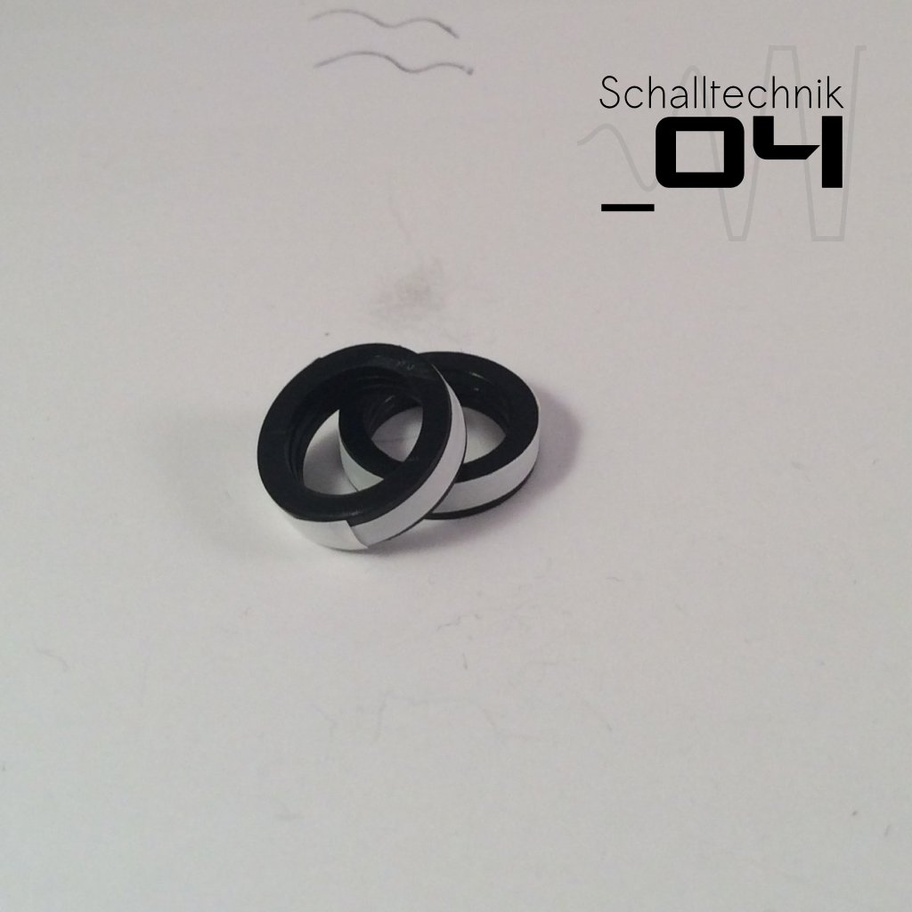 Use tape to fix three washers together. (they come with the jacks)
 Then use hot glue or super glue to glue the washers to the jacks.
If you use hot glue, make sure not to apply to much glue.
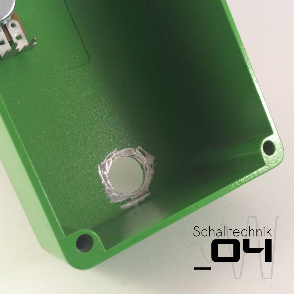 Scratch off some coating arround the footswitch-hole to ensure an electrical connection between the enclosure and the theeth washer.
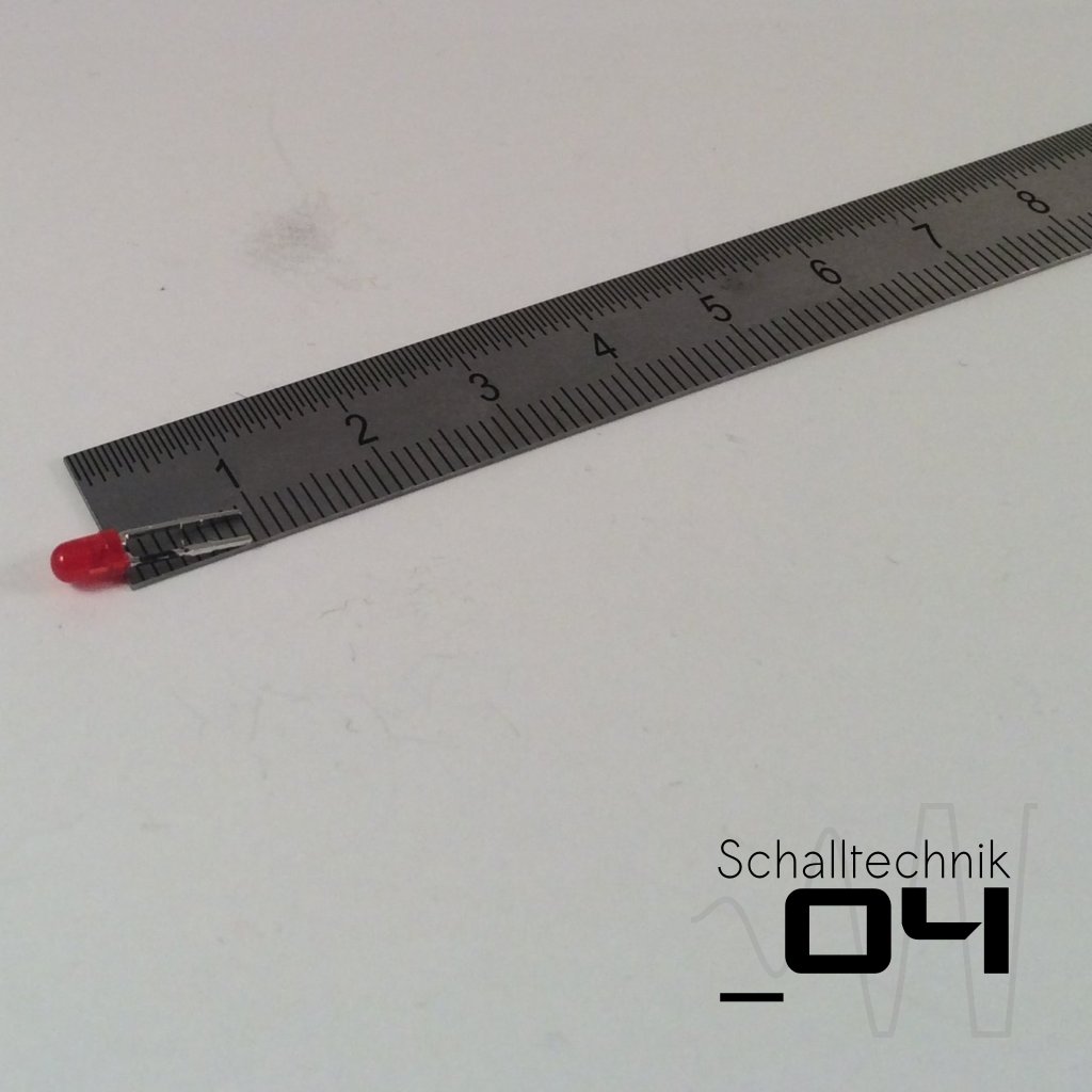 Mark one side of the LED with permanent marker and remember which side it was. Now cut the legs of the LED to 9-11mm.
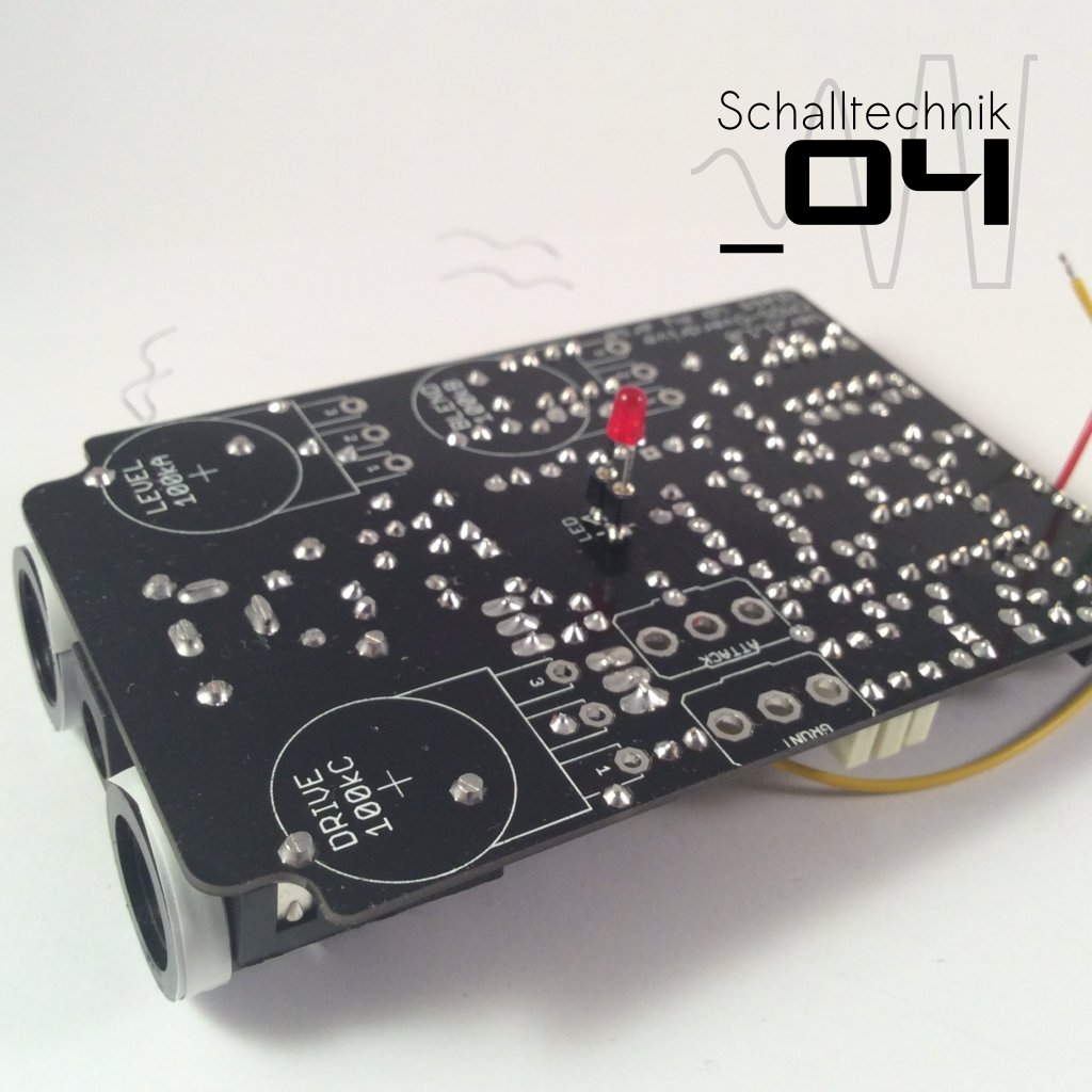 Put the LED in the socket. Align correctly!