Assembly Preparations
Contents
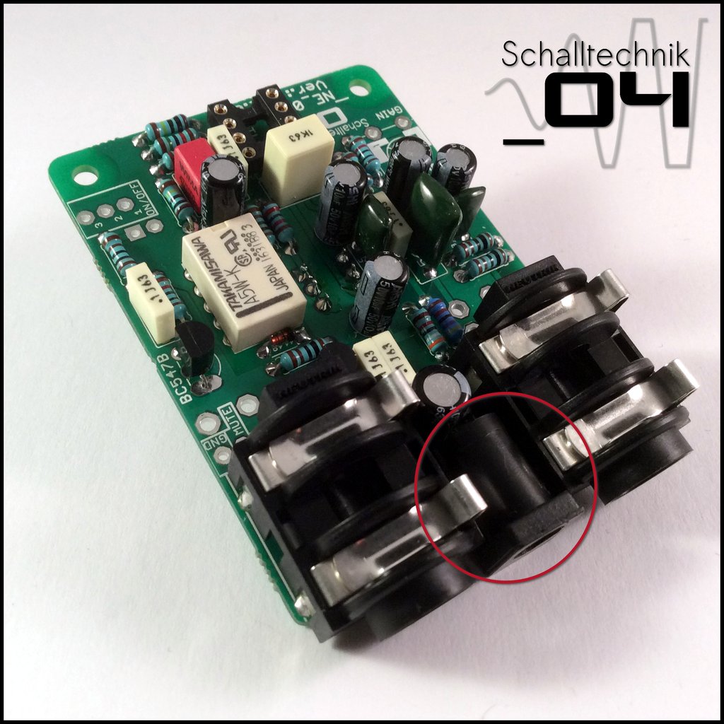
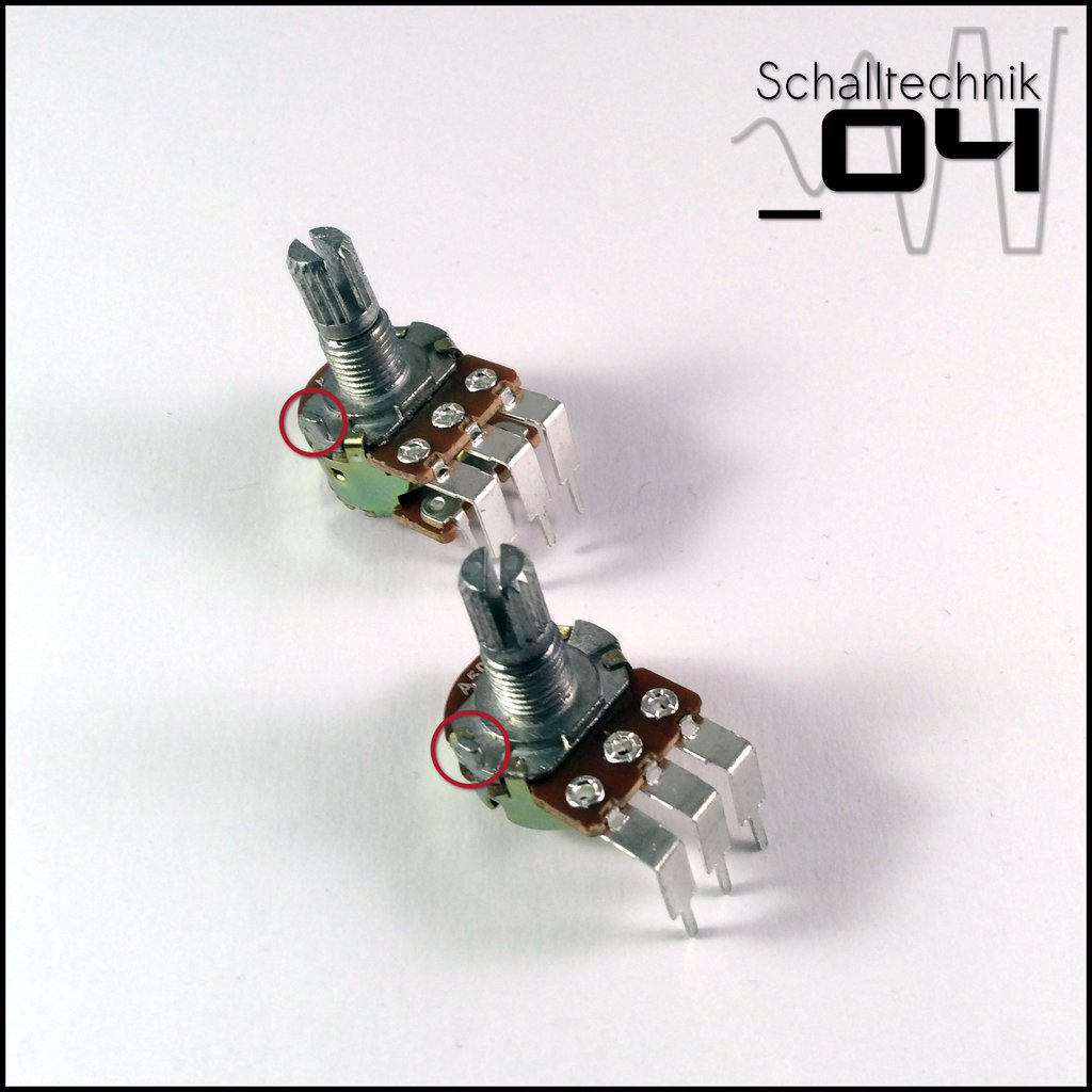 The pots are equipped with small hooks. (as seen on the picture above). They are not needed.
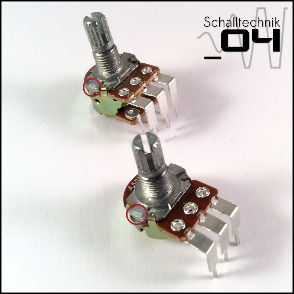
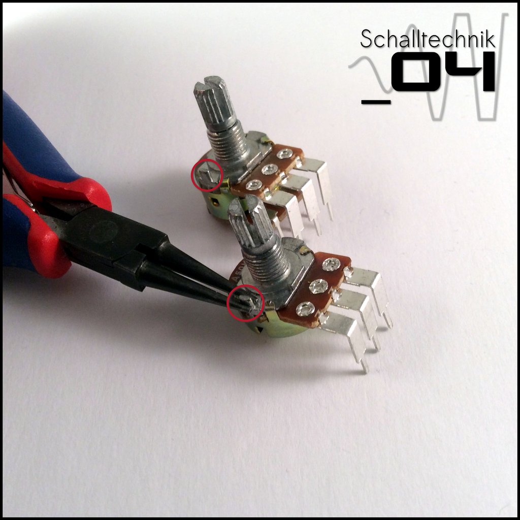 Just break them away with a pair of pliers
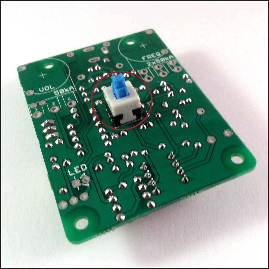 Insert the pcb push-switch (1x) and solder just 2 Pins to the PCB.
Note: The other 4 Pins of the push-switch are soldered after putting the PCB into the enclosure. That way the switch can be aligned to the hole in the enclosure.
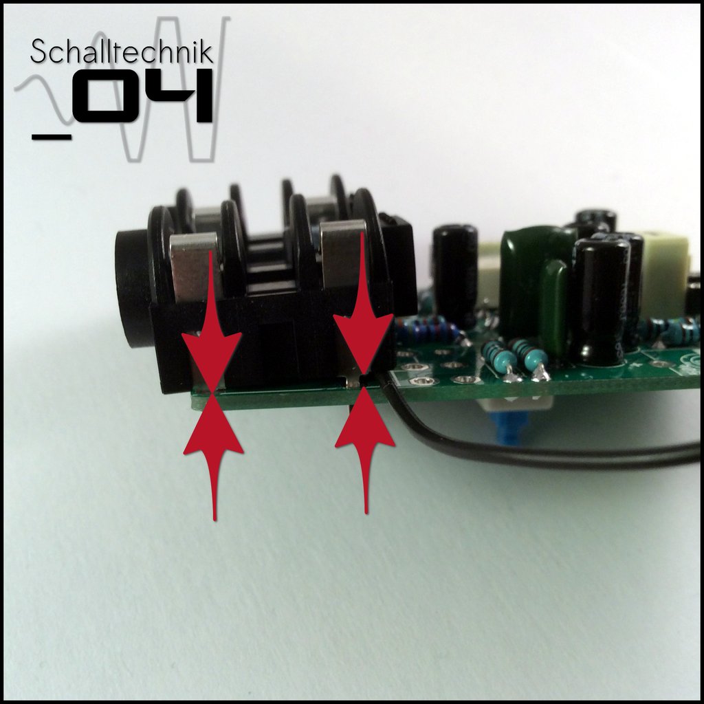
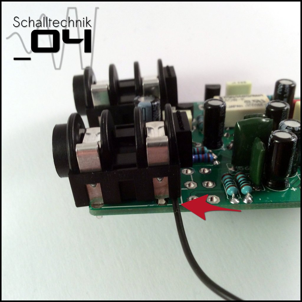 The 125B/1590N1-enclosures aren’t rectangular, thus we need to mount the input- and outputjacks with a small angle. I use a piece of wire, which I put under the jacks (see in the pictures). Then I solder them.
 Insert the dc-jack and solder it.
Note: If you like, you can cautiously clean the areas around the jacks again with PCB-cleaner.
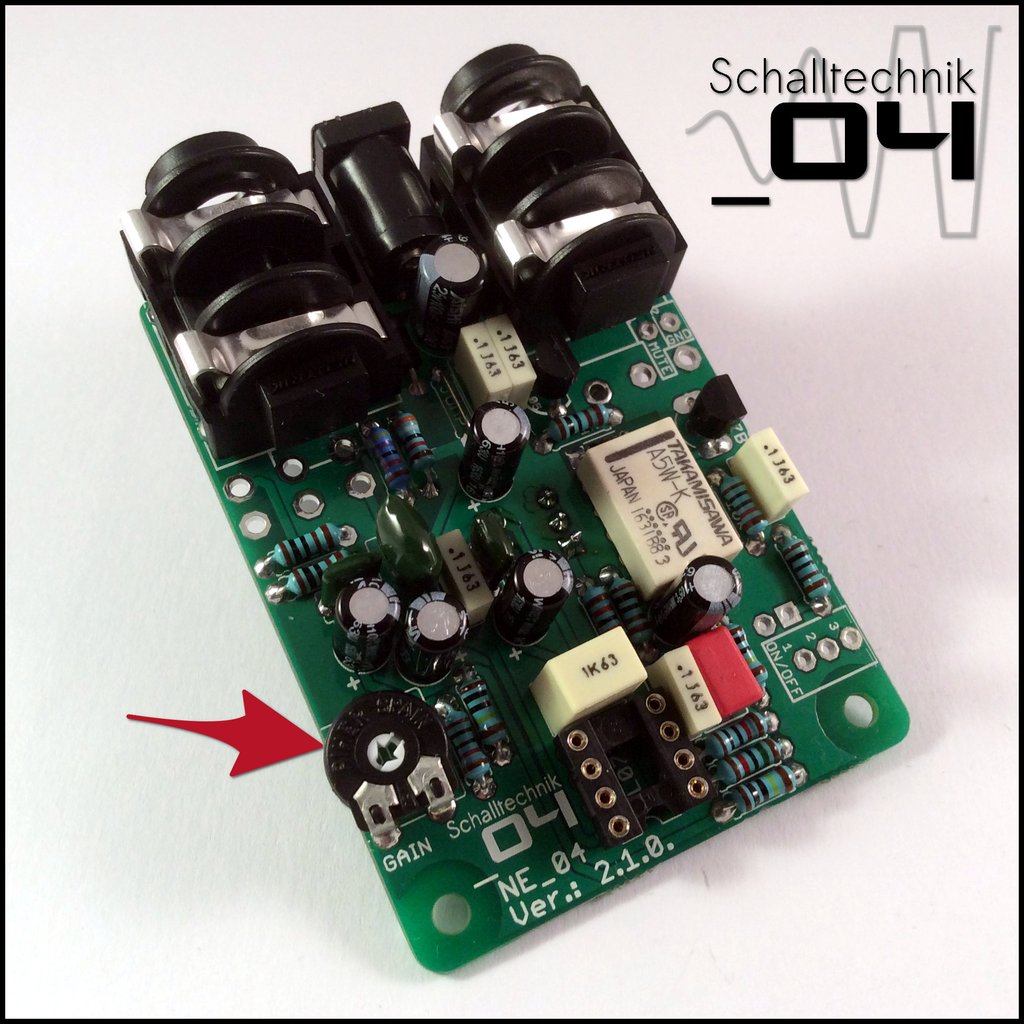 Insert the trim-pot (50k) and solder it.
Set the trim-pot – as seen on the picture – to minimum. In this configuration it’s acting as a buffer with 0dB. The further the trim-pot is turn up, the high will be the amplification of the signal. The Volume Pot on the outside is just a pad at the end of the effect. Meaning: If you are overdrive the effect with a to strong signal and also boost it the with the trim-pot, you won’t be able to remove this distortion with the Volume-Pot on the outside. If you want to this kind of boost without overdriving the pedal, just increase the input-voltage to up to 18V.
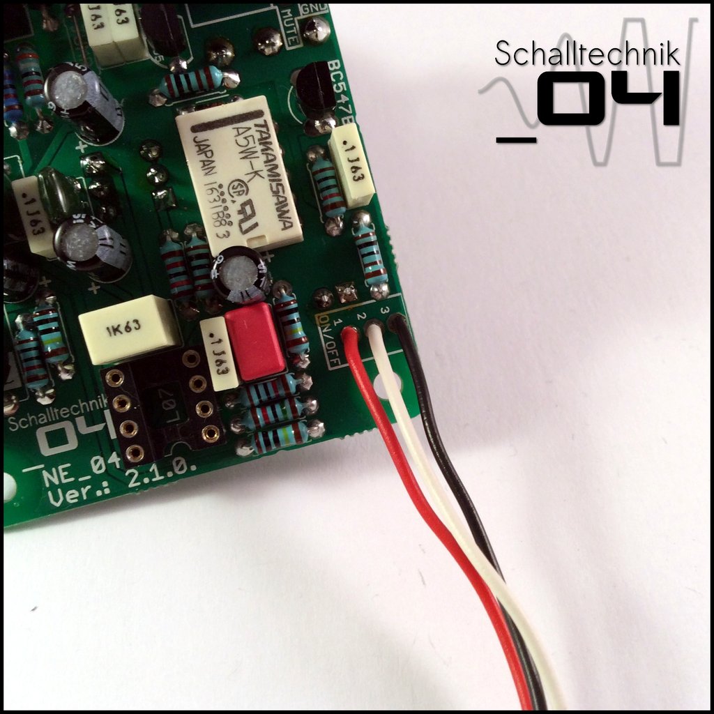 Solder wires to the “ON/OFF”-Port.
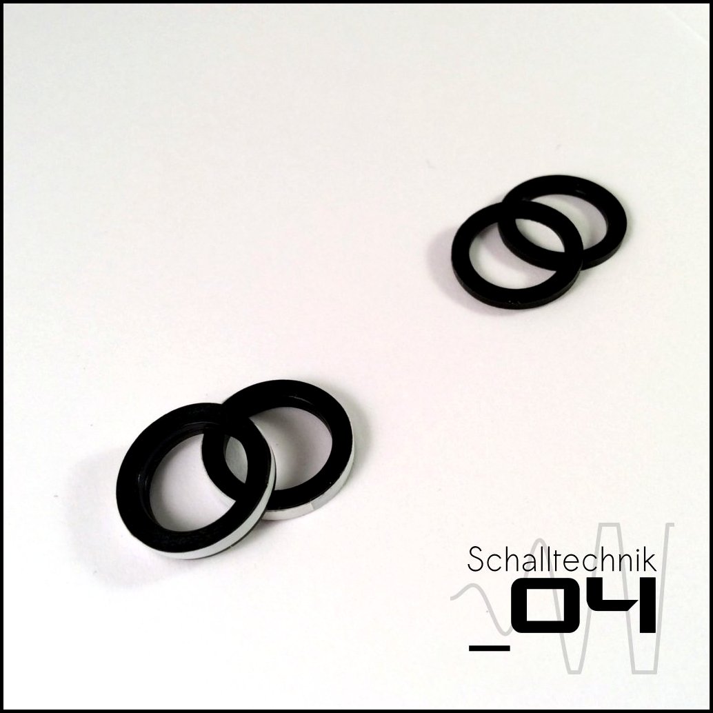 Use tape to fix two or three washers together. (they come with the jacks)
Then use hot glue or super glue to glue the washers to the jacks. If you use hot glue, make sure not to apply to much glue.