Assembly
Contents
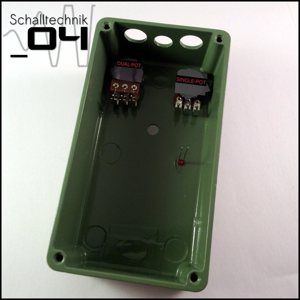 Screw the pots in the enclosure. Put two layers of tape on the pots to ensure the housing can’t touch the soldered points.
Insert the led into the enclosure.

The anode (+) has to be on the left side.
Take the pcb and lead through the pins from above.
This methode seems to be tricky, but in my case it always worked after the second or thrid “take the PCB out, bend the pins a little bitte, put the pcb in again”: ?
Important here: Don’t use force!
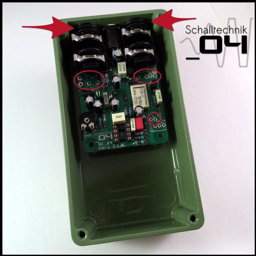 If everything fits, tighten the nuts of the jacks…
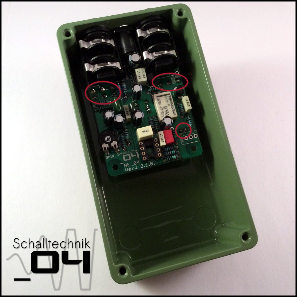 and afterwards solder the pots and the led to the pcb then screw the other nuts tight.
Now: Add the cap to the push-switch. Then by reheating the already set solder joints try to fit the switch to the enclosure. After that solder the missing 4 Pins to the PCB.
No picture available.
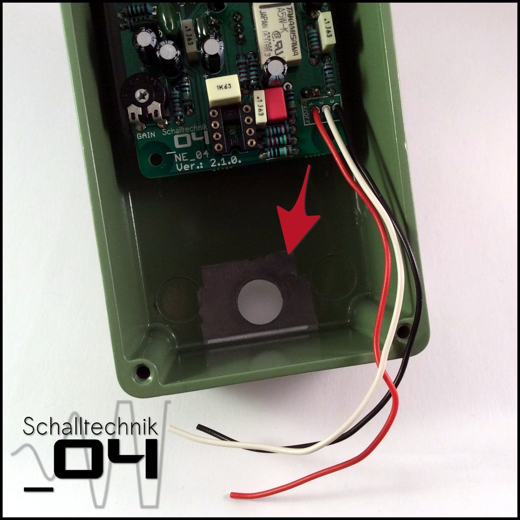 Now we remove the tape we’ve put on before painting.
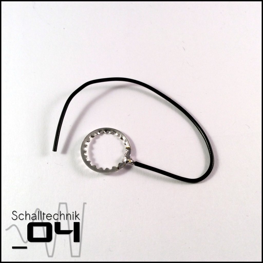 Now we take the tooth washer which comes with the footswitch and solder a wire to it.
About shielding:
If we ground the enclosure it will act like a shild. Ungrounded the shielding effect is much smaller.
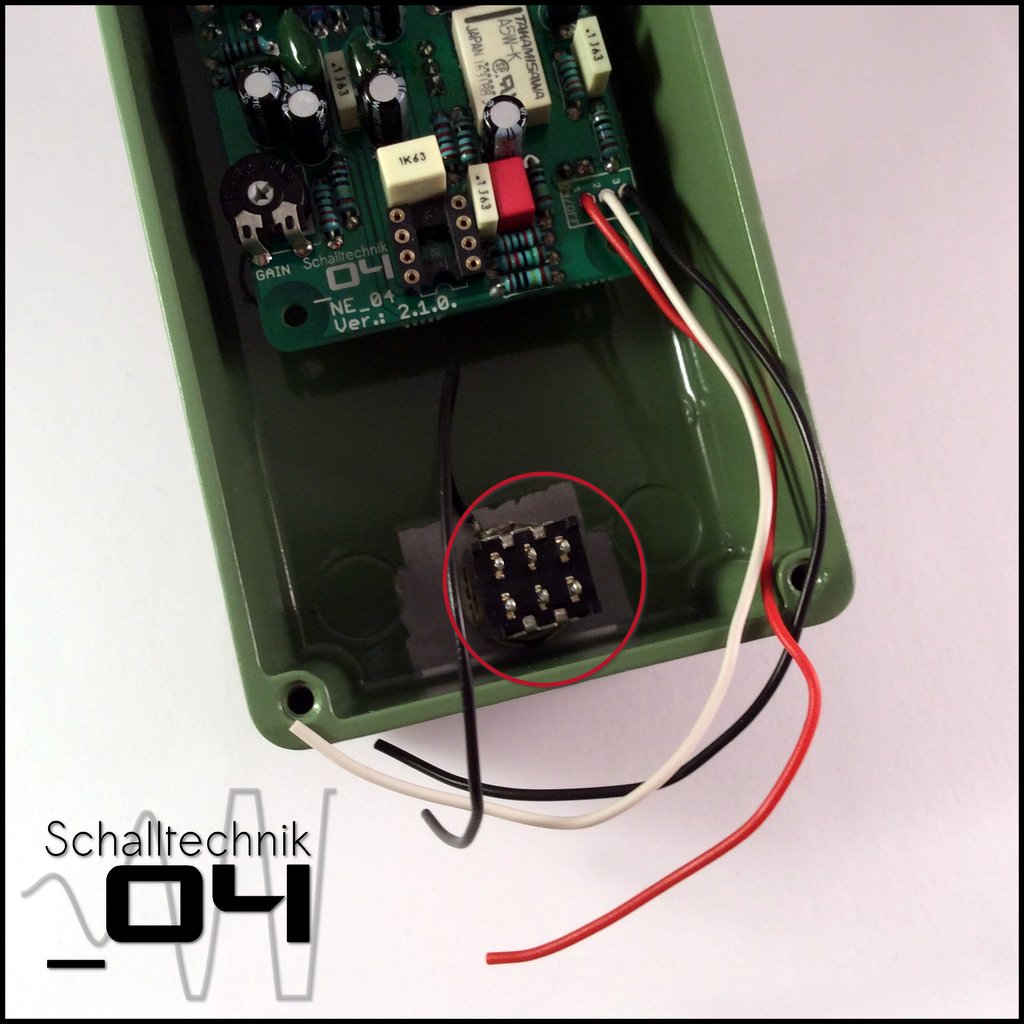 Now mount the foot-switch with the teeth washer…
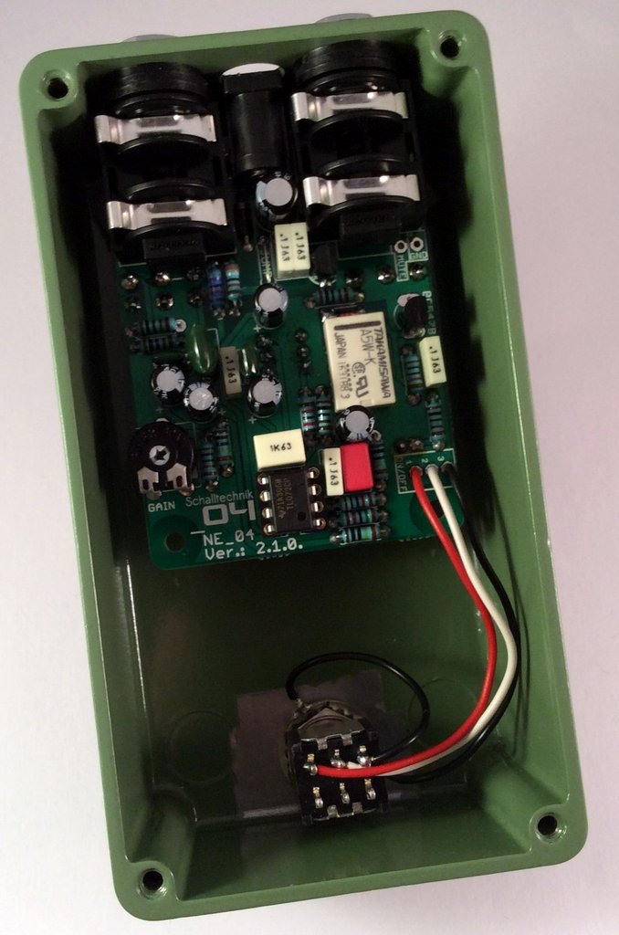
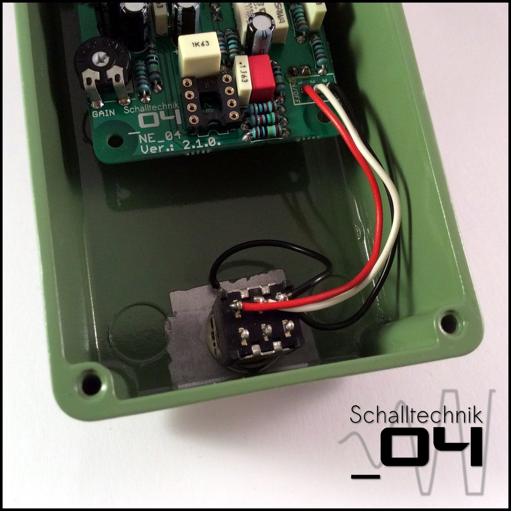 …and solder the cables from the “ON/OFF”-port to the footswitch. The cable vom the teeth washer gets soldered to the same pin as the cable from “ON/OFF”-Port PIN3. (here: black)
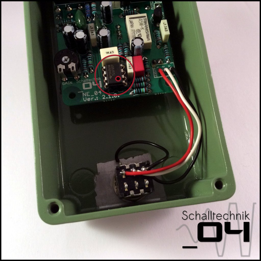 At the very end you can insert the TL072. Align correctly!
While inserting the ICs try to stablise the pcb by supporting it with your finger(s) under the pcb.
That’s it! We’re done. Time for testing! ?