Assembly Preparation 2/2
Contents
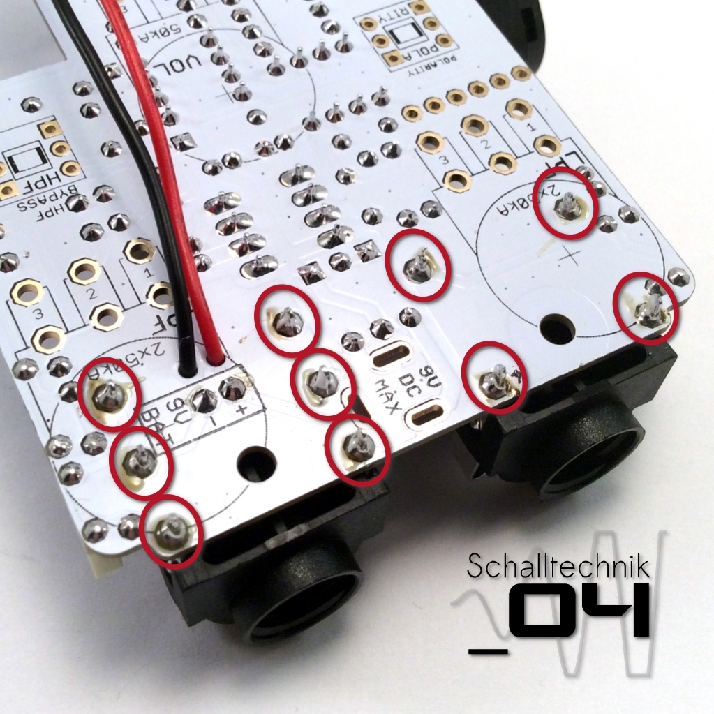
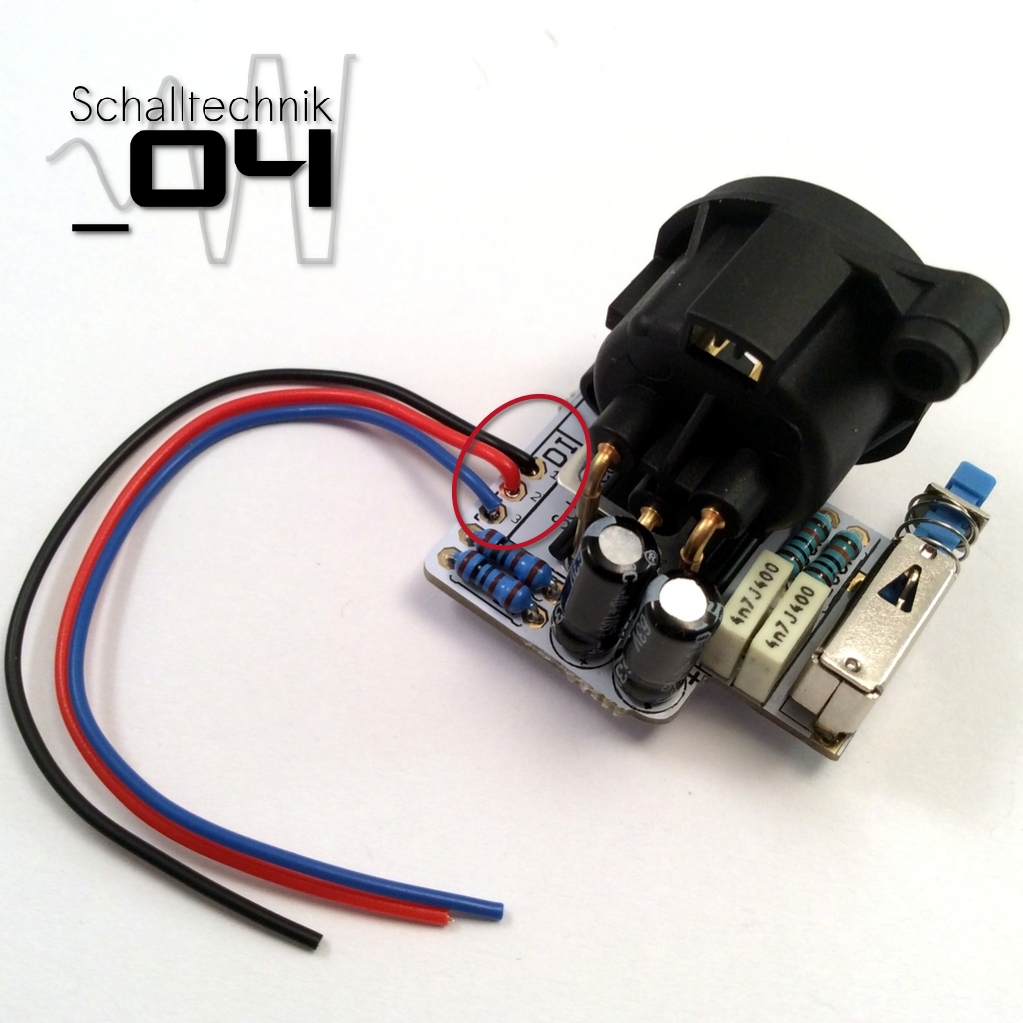
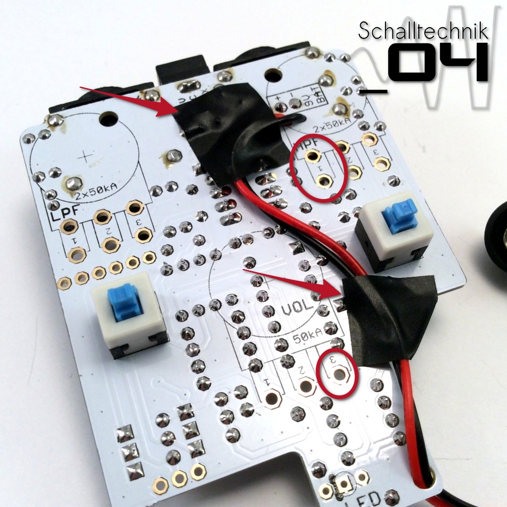
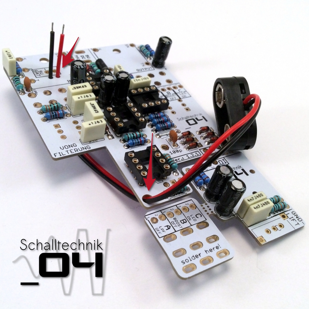 Add the wires of 9v battery clip – as shown in the picture above – to the pcbs.
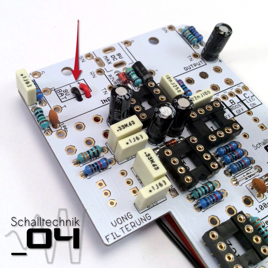 …and solder the ends of the wires to the pcb. (red +, black –)
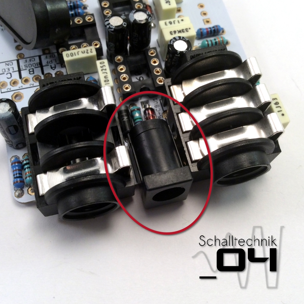
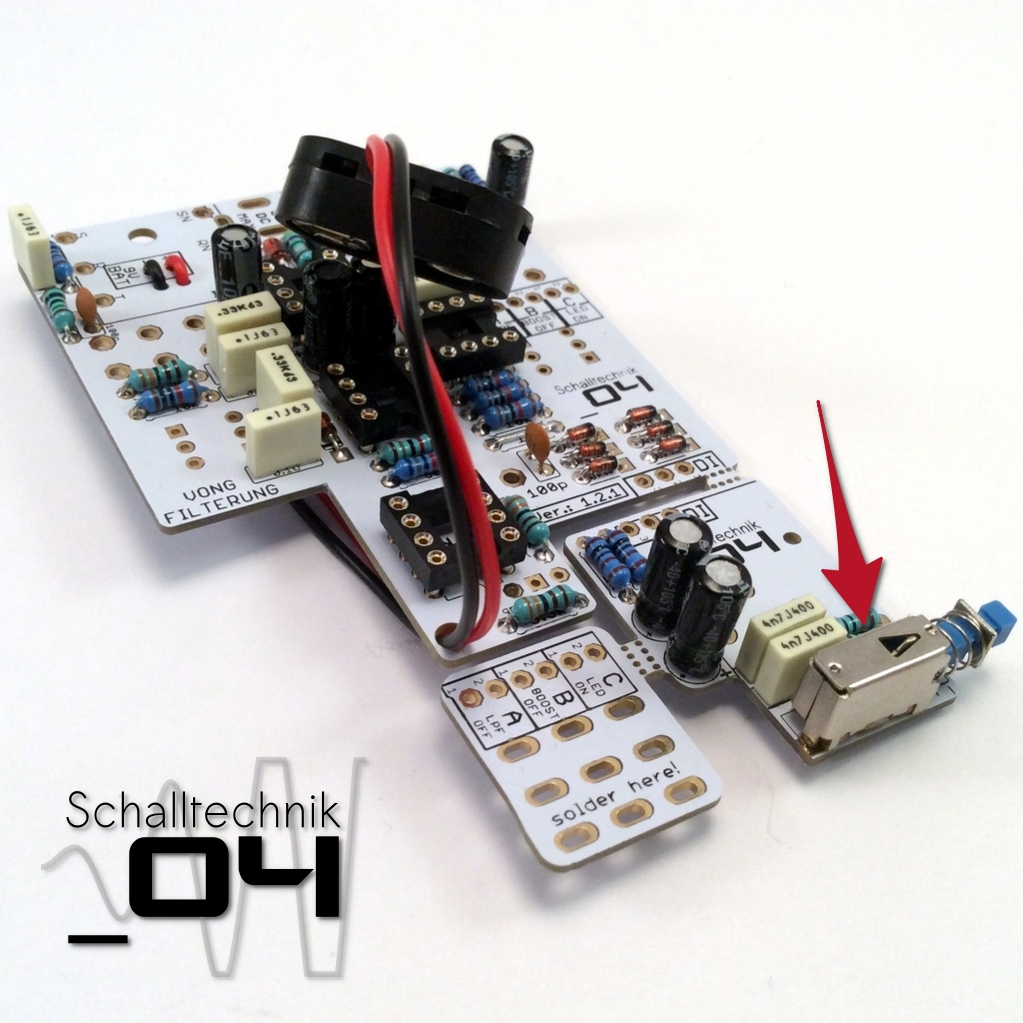 Insert the ground-lift switch and solder it. Take care that it gets soldered in straight. It gets important later.
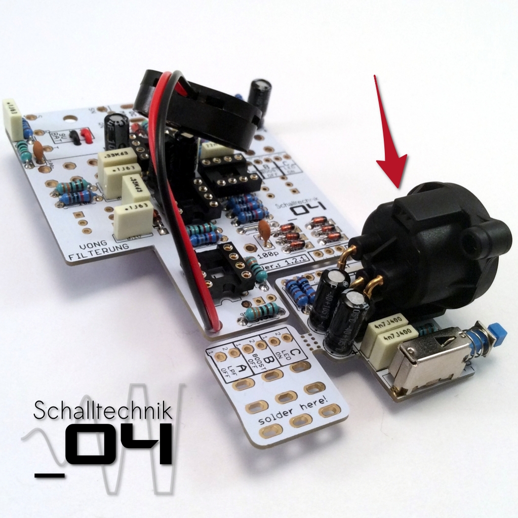 Insert the xlr jack and solder it. Try to press the jack onto pcb, until the jack is sitting completely flat on the surface of the pcb.
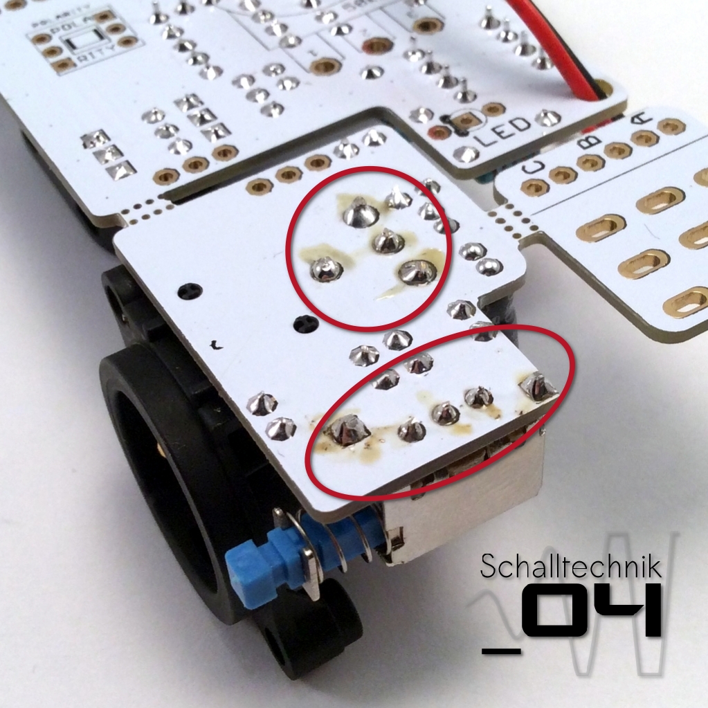 Cut the legs of the xlr jack and the ground-lift switch and reheat the solder joints.
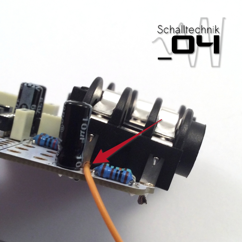
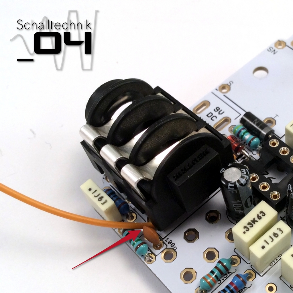 The 125B/1590N1-enclosures aren’t rectangular, thus we need to mount the input- and outputjacks with a small angle. I use a piece of wire, which I put under the jacks (see in the pictures). Then I solder them.
To avoid mistakes please insert the stereo jack first!
 Cut the legs of the jacks…
 …and reheat the solder joints.
 Insert the dc-jack and solder it.
Note: If you like, you can cautiously clean the areas around the jacks again with PCB-cleaner.
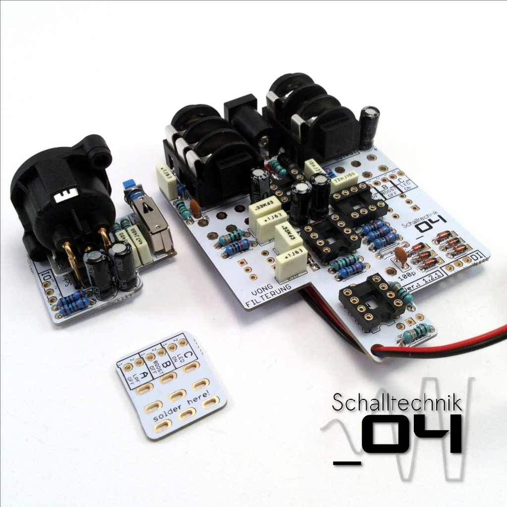 If the pcb hasn’t already falling to pieces, know is a good time to break the boards apart.
 Solder wires to the XLR PCB
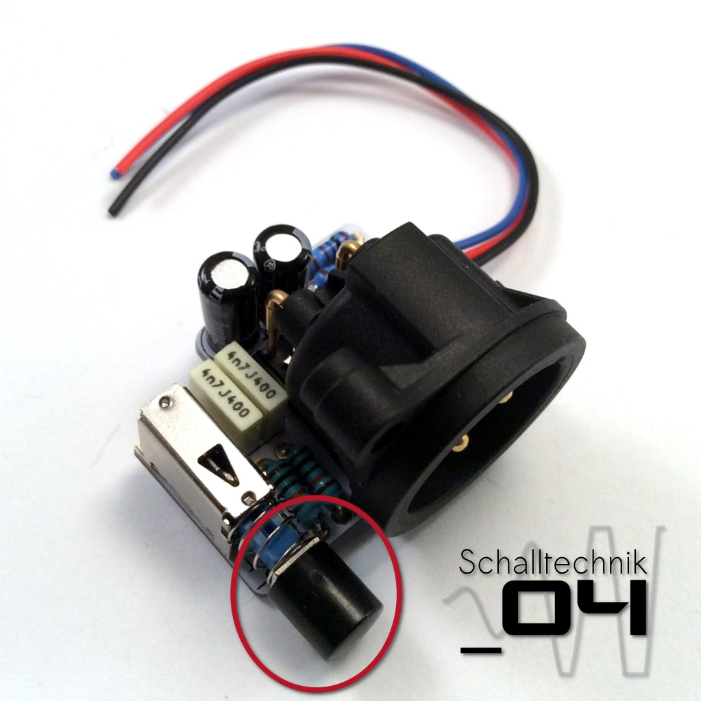 Add the cap to the switch. (Don’t try to remove it again!)
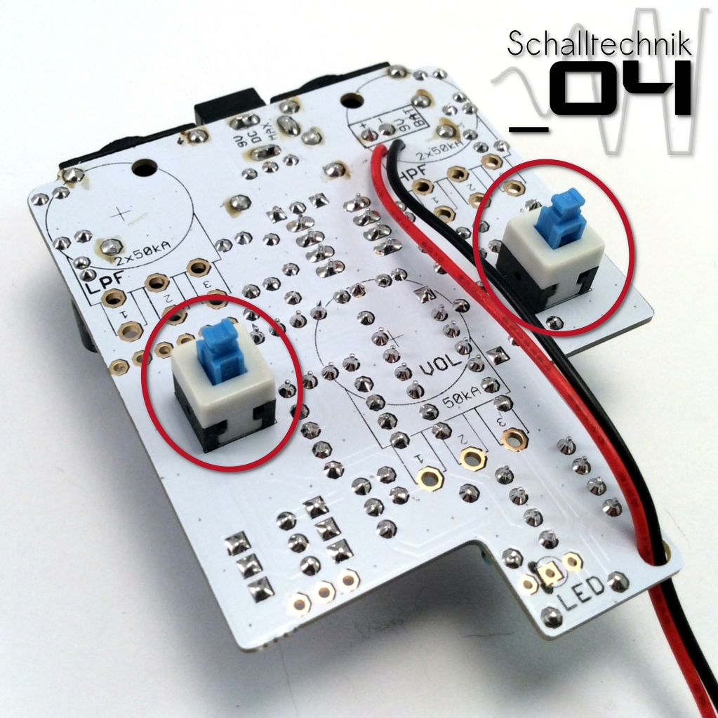
 Insert the footswitch and solder it.
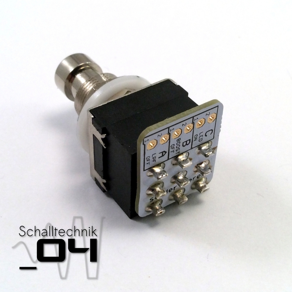
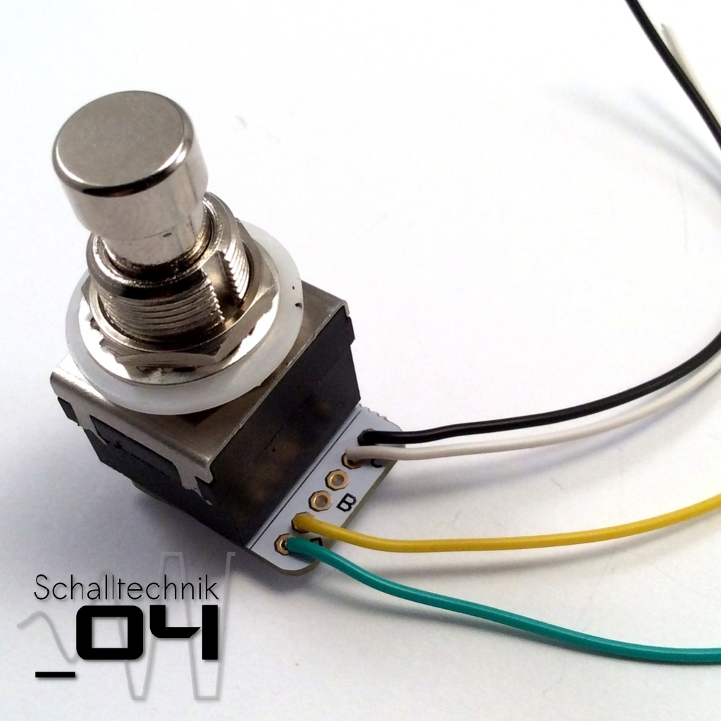
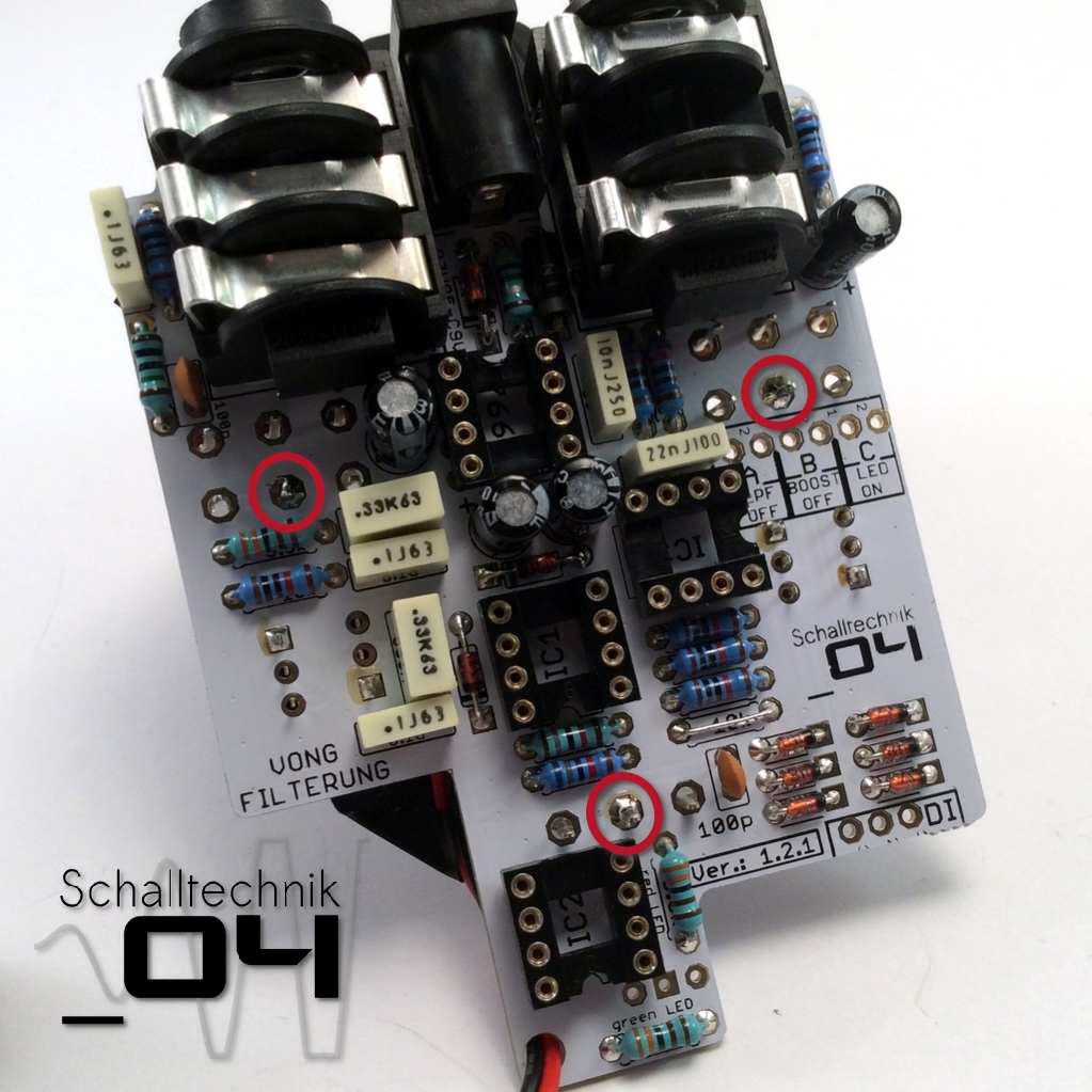
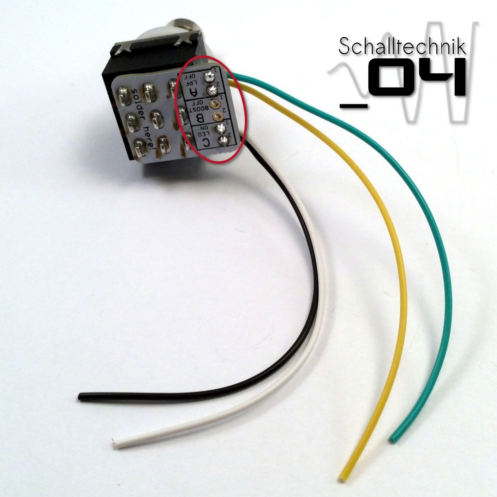 Now wire the footswich pcb as you wish.
The labeling is quite self explaining; so:
- Port C turns the LED on/off – I guess that’s a desired option for most builders
- Port B turns the volume pot on/off -> only useful, if the 10k resistor was inserted
- Port A turns the LowPass Filter on/off
If PORT A or B stays open (not wired), the corresponding function is permanently active.
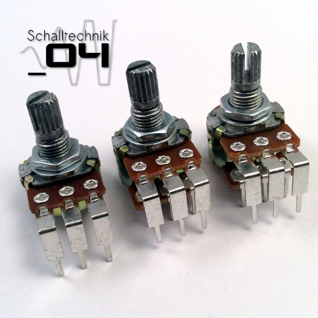
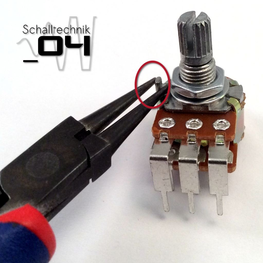 The pots are equipped with small hooks. (as seen on the picture above). They are not needed. Just break them away with a pair of pliers
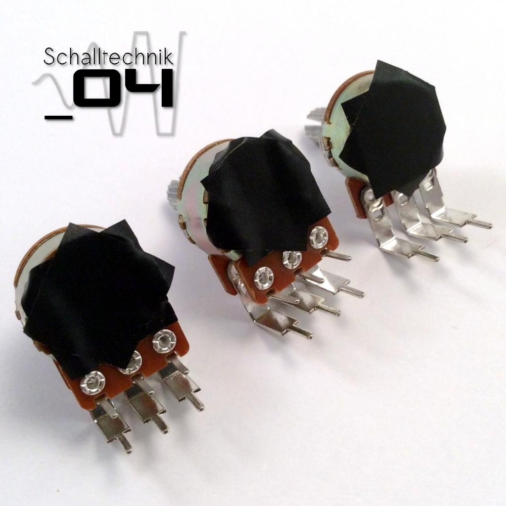 Put two layers of tape on the pots to ensure the housing can’t touch the soldered points.
 Insert the DPDT-Switches, but (!) …
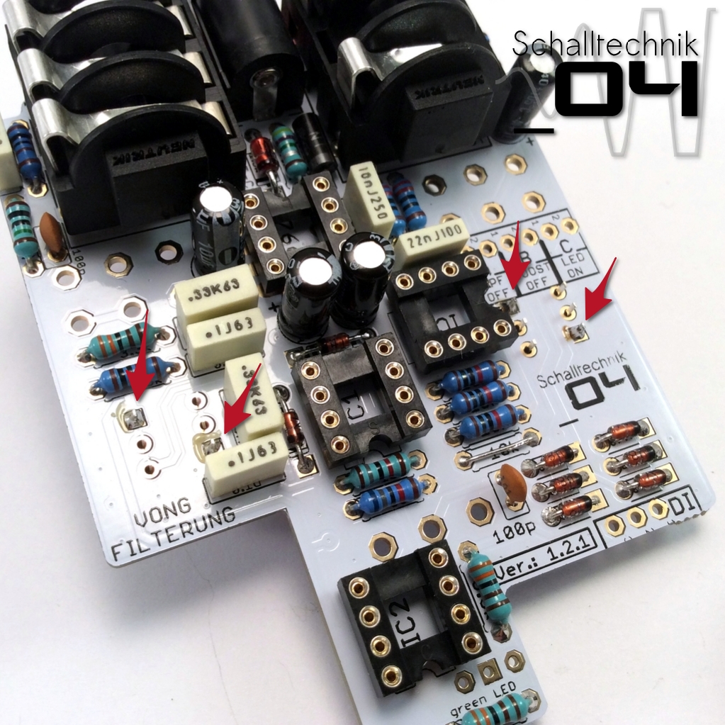 … solder just two joints each.
 Fixate the battery cable with some tape that way to ensure that the wire won’t get damaged while soldering the pots later.
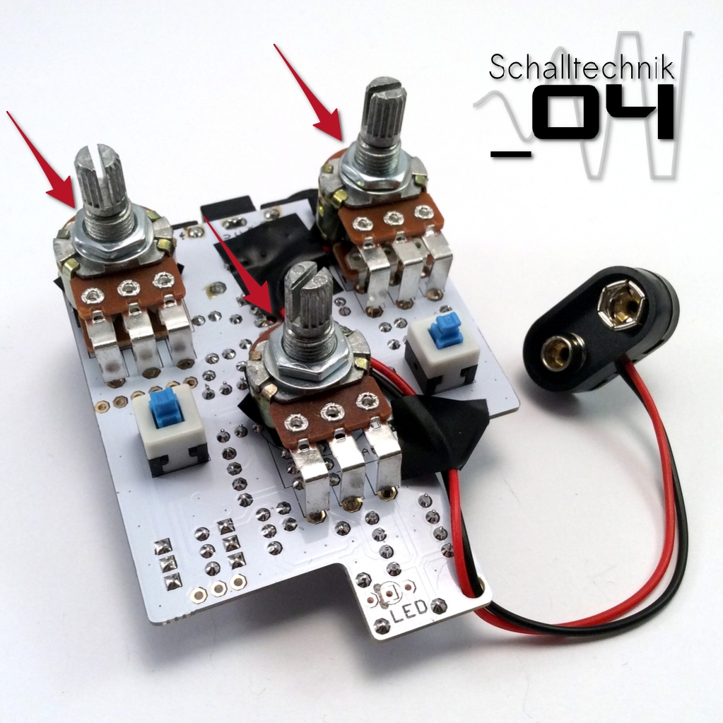 Insert the pots, but (!) …
 … solder just one connection each
 Use tape to fix two to three washers together. (they come with the jacks)
Then use hot glue or super glue to glue the washers to the jacks. If you use hot glue, make sure not to apply to much glue.
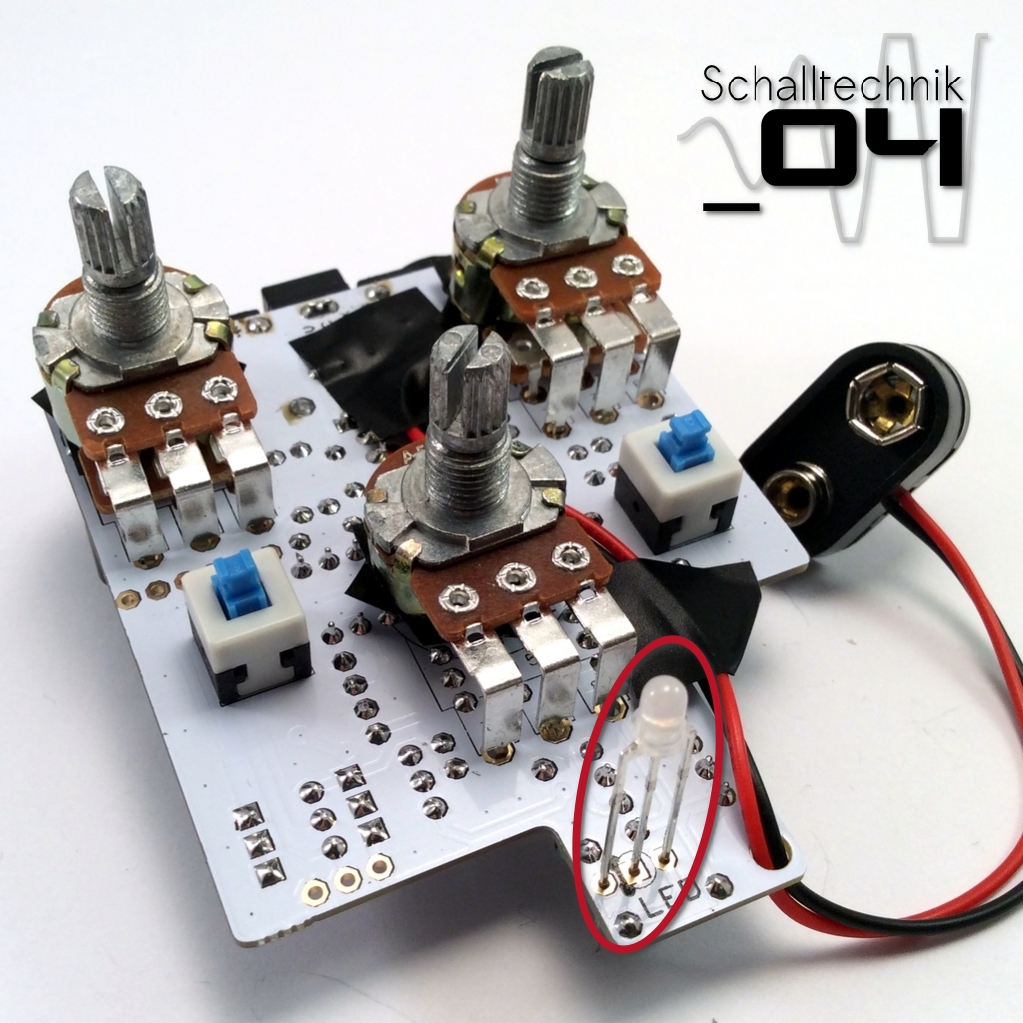 Remove the nuts and washers from the pots and insert the LED. Don’t solder it yet!
Align correctly! The lower part of LED-Case is flattened on one side; that side goes to the black bar on the pcb.