Assembly Preparations
Contents
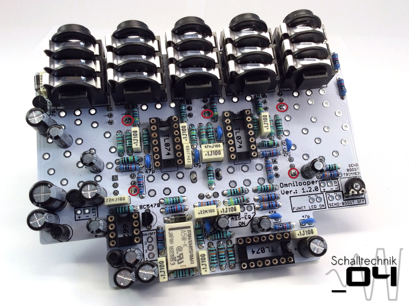
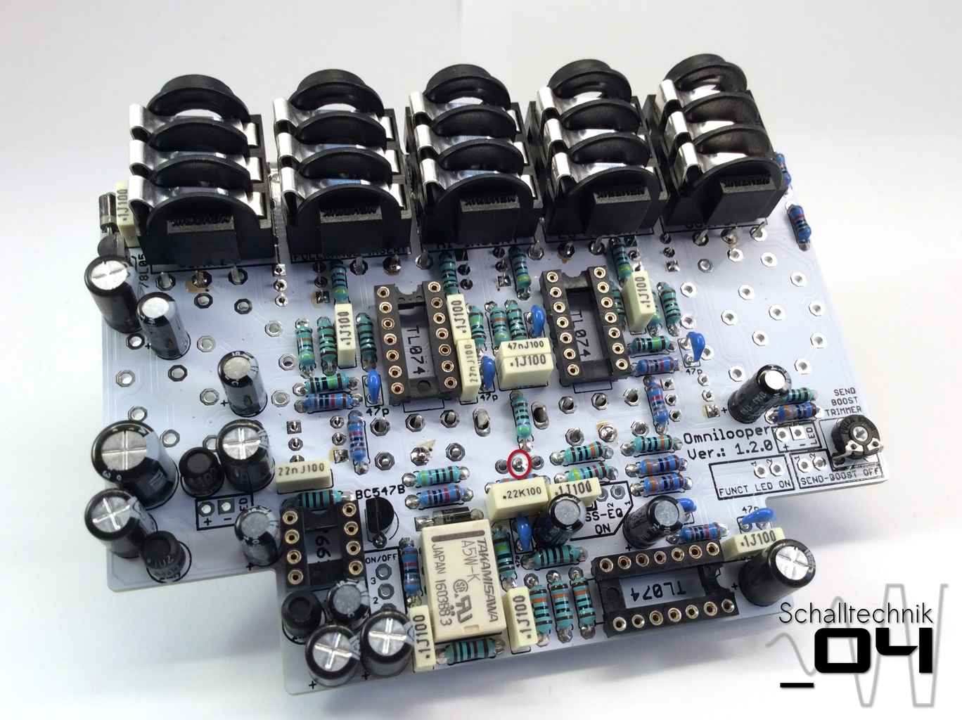
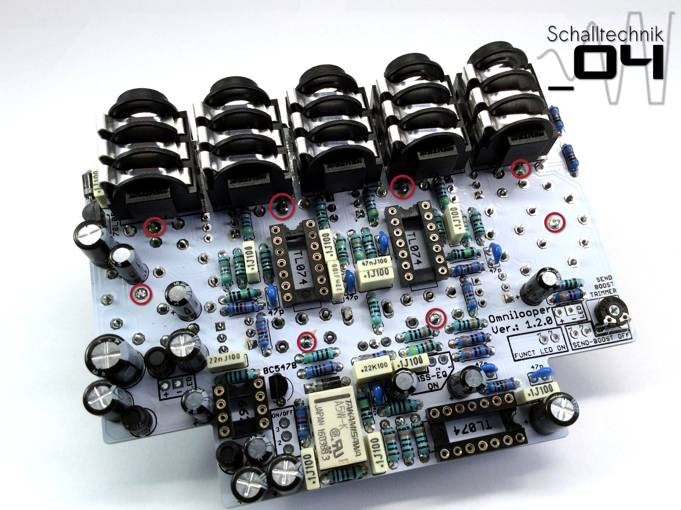
Hint: At this point, it is highly recommended to check the PCB and the solder joints. Some solder joints aren’t accessible after complete assembly. If considered that 95% of all issues are related to bad/cold solder joints, it is worth investing 5-10 min now to check every solder joint.
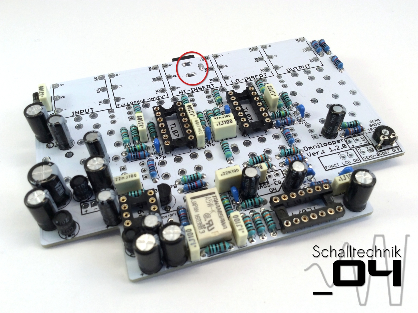
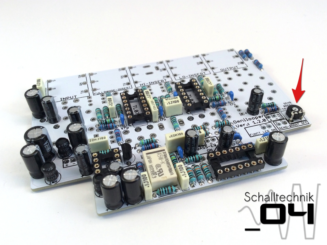 Insert 50k trim pot, solder it and set it to minimum (7 o’clock)
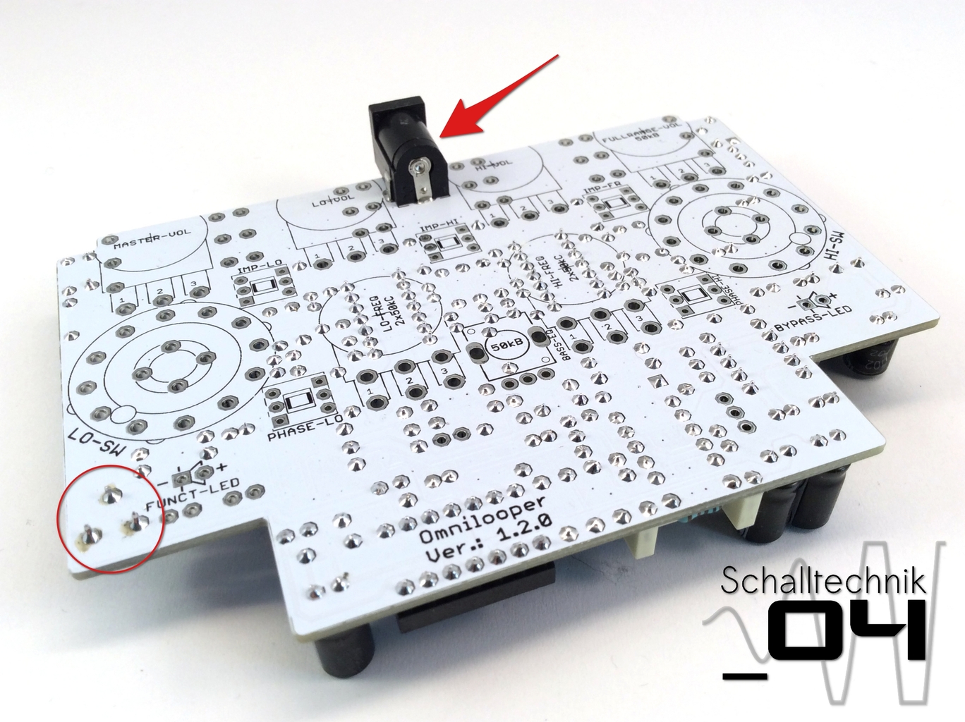
Clean the solder joint of the trim pot carefully, let it dry and insert and solder dc-in-jack to the PCB.
Take care that it is soldered in straight!
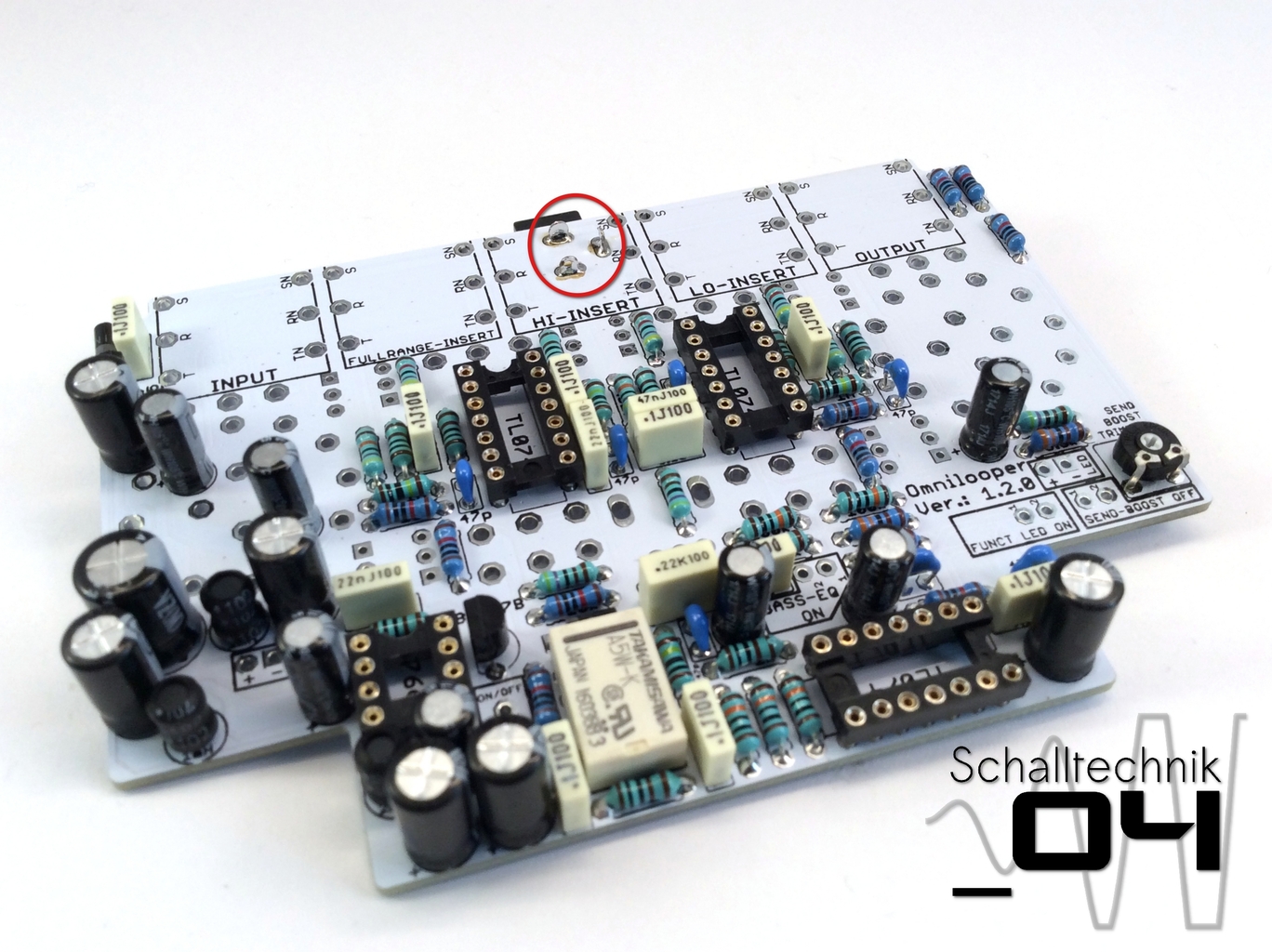 Shorten the ends of the dc-in-jack,…
 …reheat the joints,…
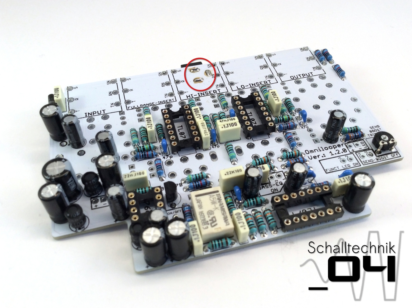
 …clean them and let them dry.
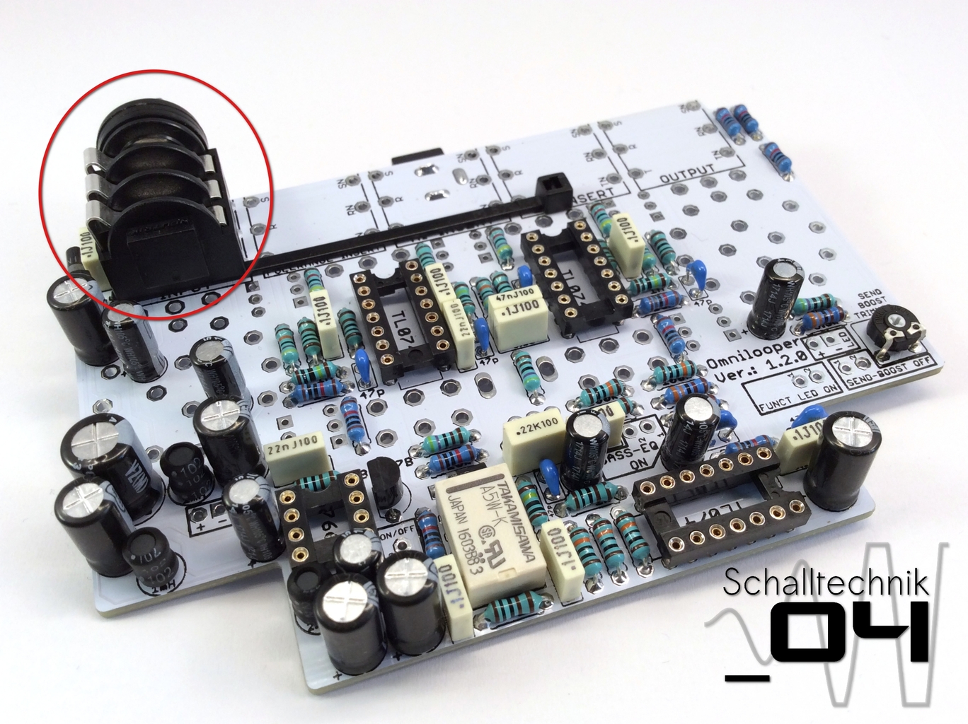
The BB2-enclosures aren’t rectangular, thus we need to mount the 1/4″ jacks with a small angle. Use the cable tie as a spacer as shown in the pictures. Then I solder the jacks to the pcb.
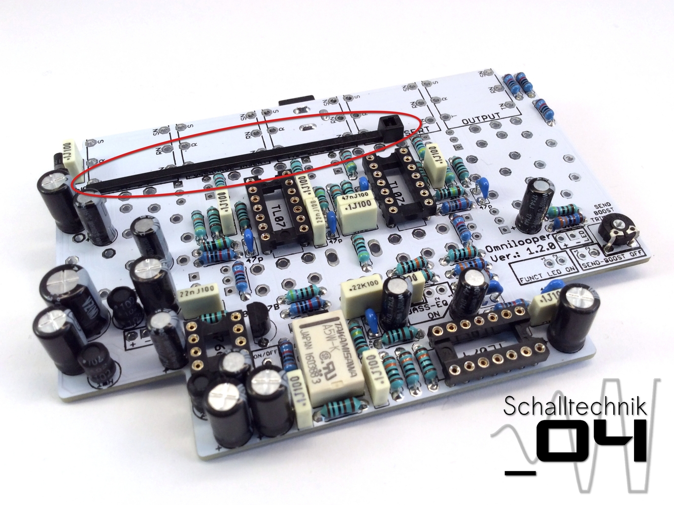
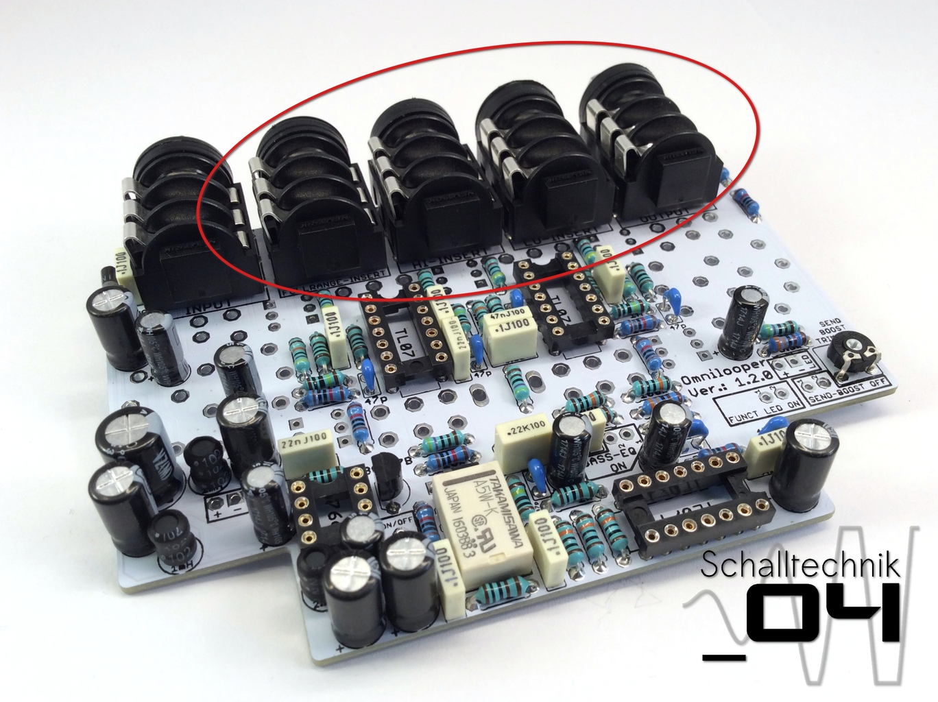
After soldering the cable tie can be removed and used as spacer for the next jack.
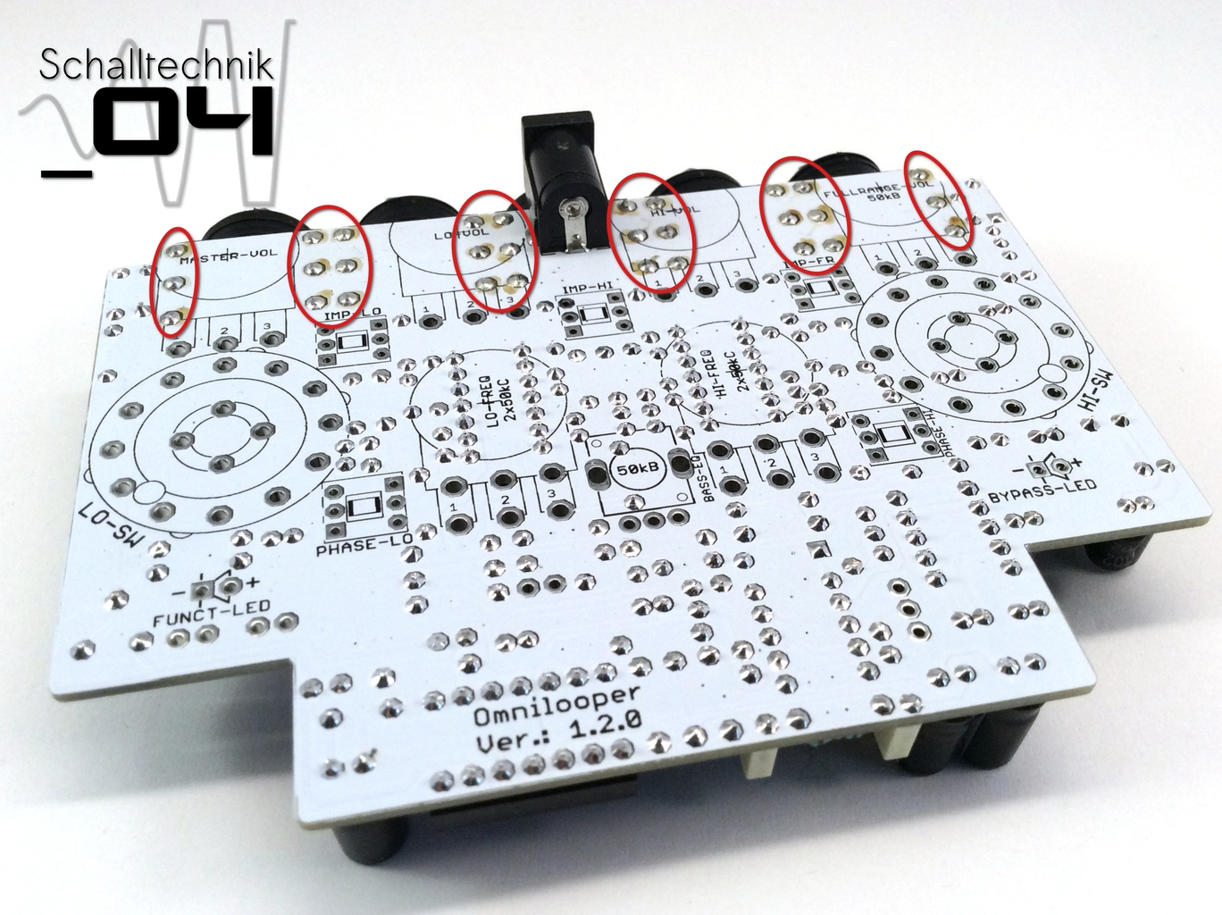
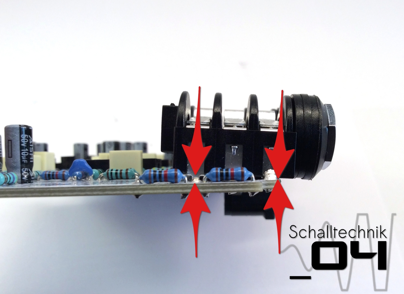
Shorten the ends of the 1/4″-jack, reheat the solder joints.
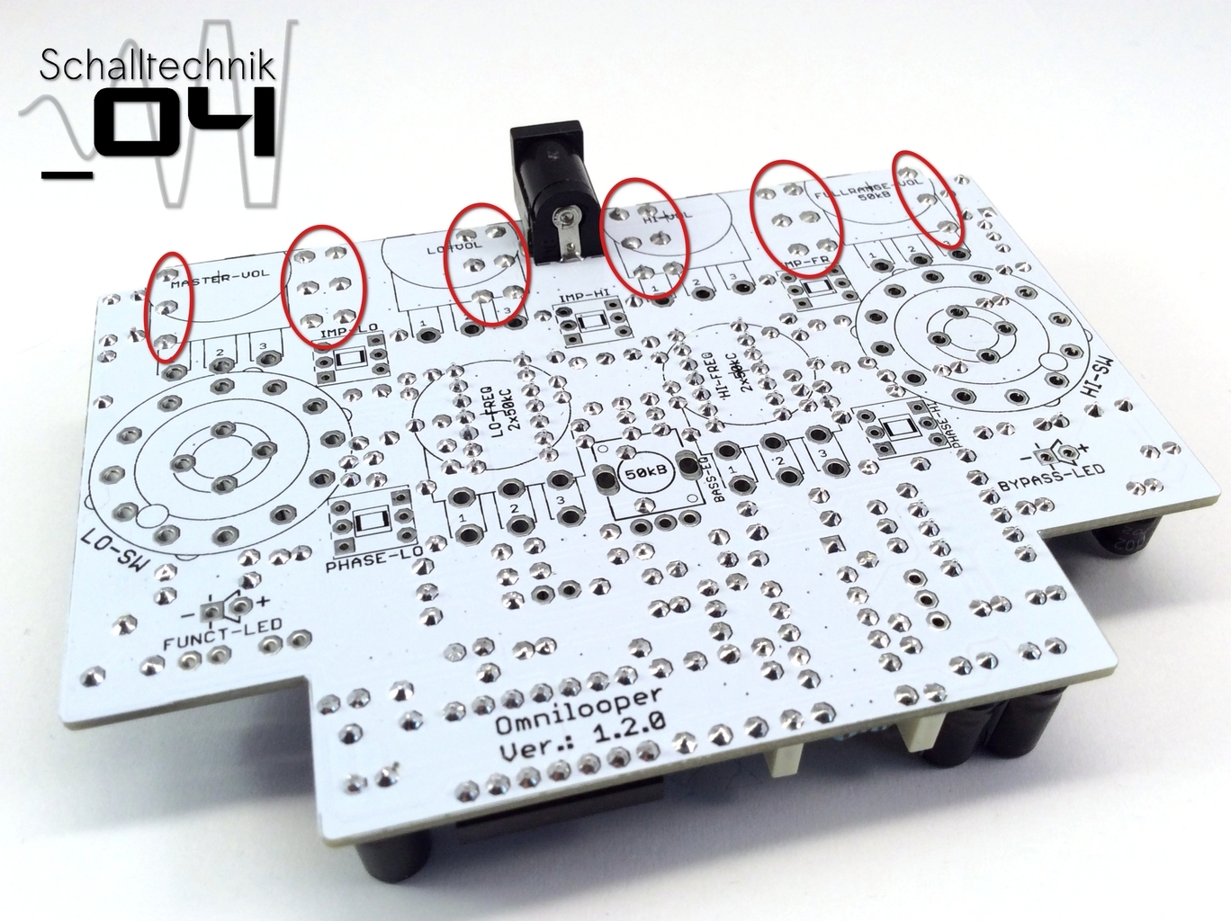 Clean the solder joints and let them dry.
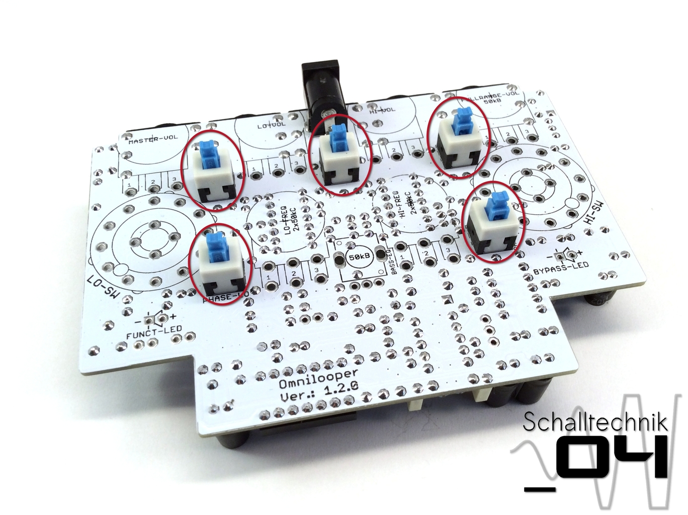 Insert the DPDT-Switches, but (!) …
 … solder just one joint each.
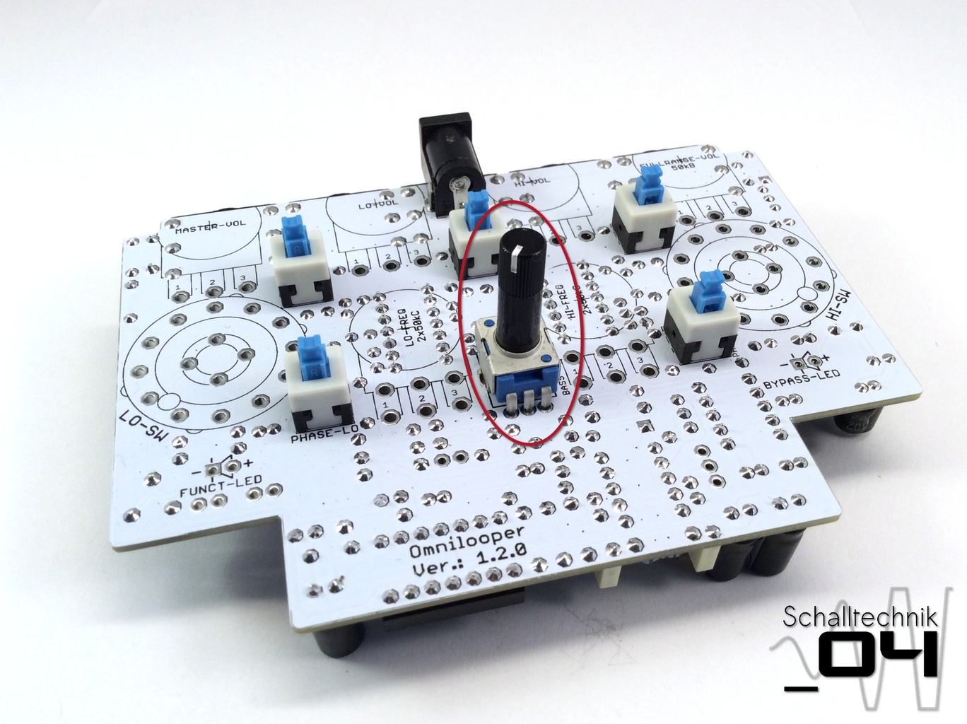 Insert bass pot (50k print), but (!) …
 … solder just one joint to the pcb.
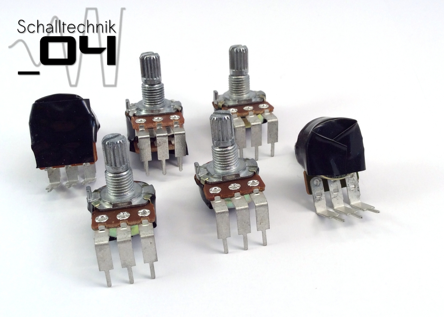 Put two layers of tape on the pots to ensure the housing can’t touch the soldered points. Remove the nuts and washers.
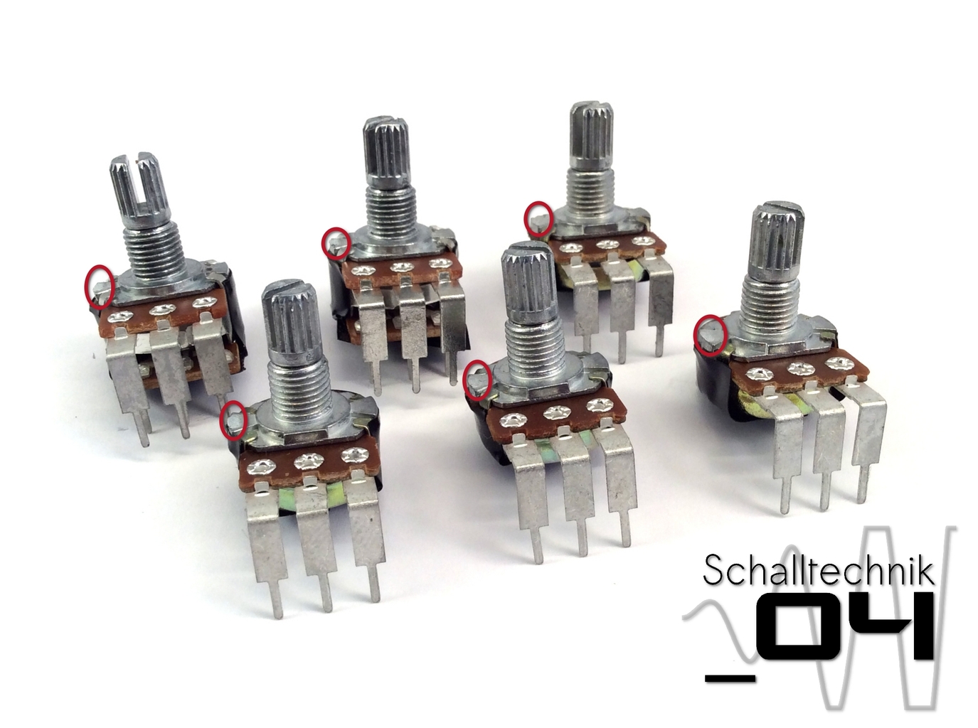
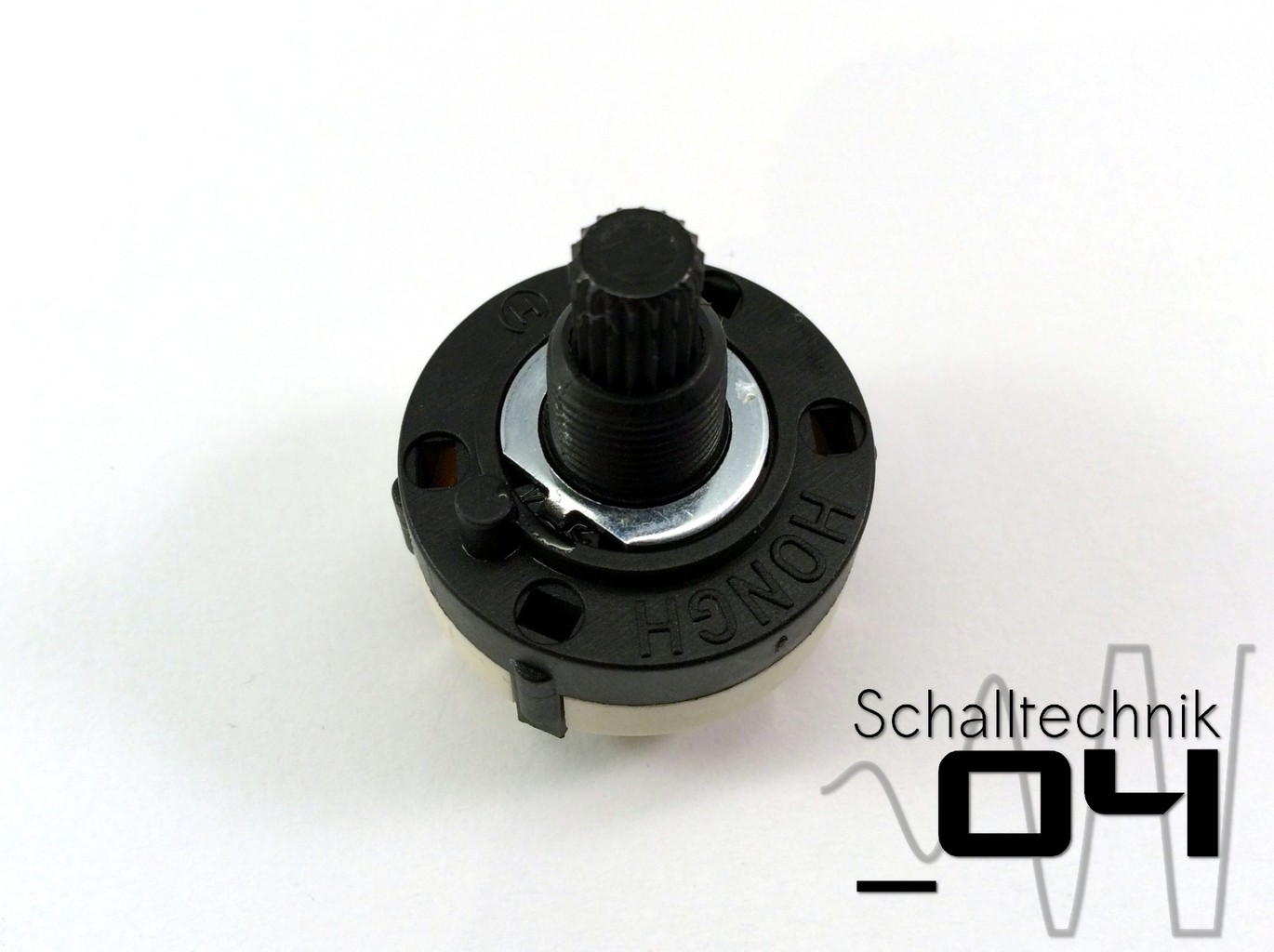
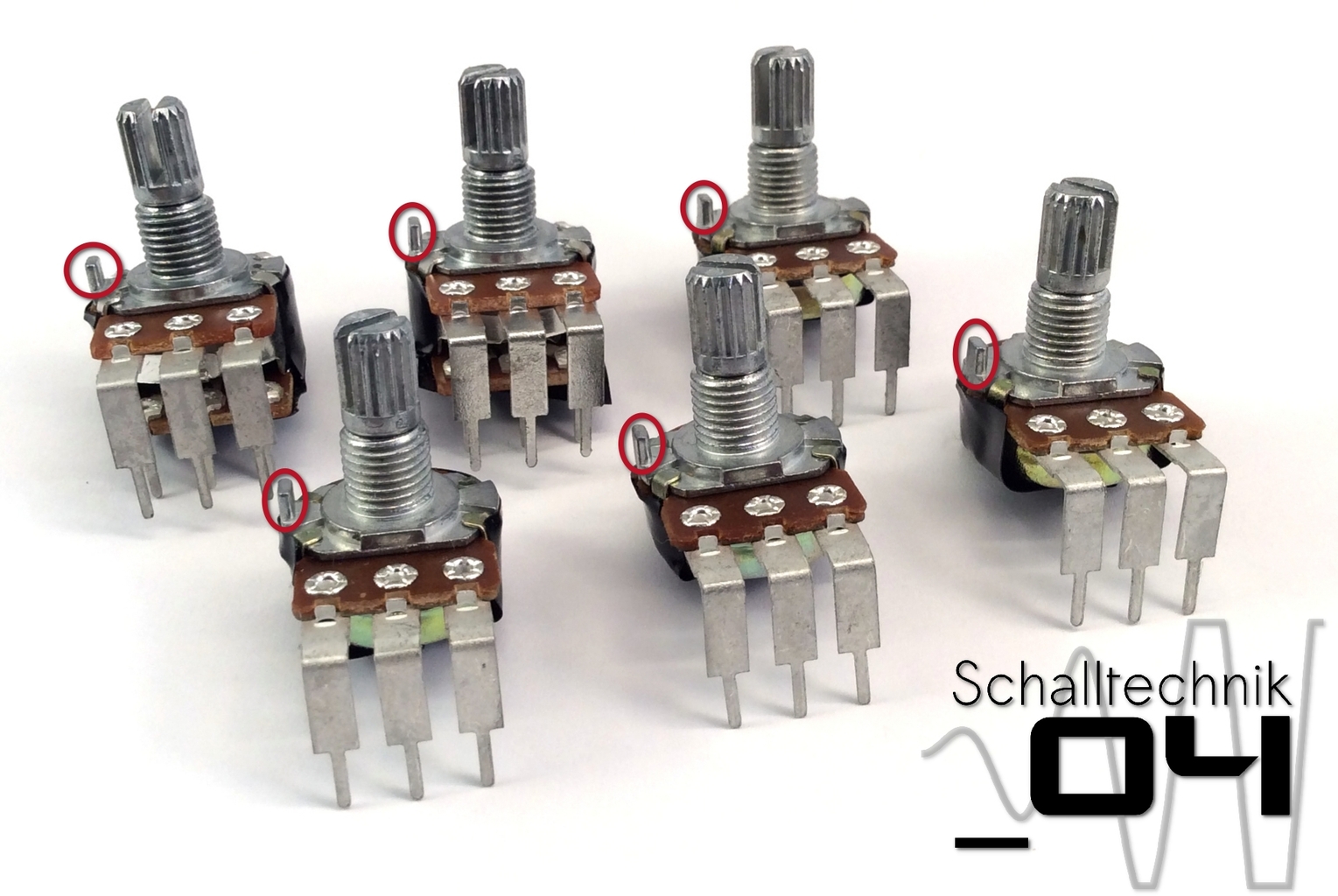 The pots are equipped with small hooks (as seen on the picture above). They are not needed. Just break them away with a pair of pliers
 If the kit was ordered directly at schalltechnik04.de, this step can be skipped.
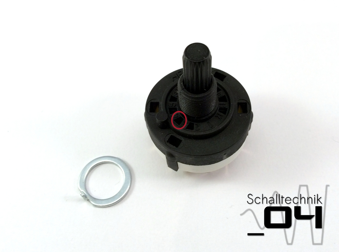
This step it only necessary with some rotary switch types, if the locking washers (left on the picture) weren’t clued in. Depending on manufacturer this washer is sometime just inserted without glue.
Procedure: Turn the axis completely counterclockwise …
 …insert the locking washer into the second hole (marked “3”)…
 …and fix it with some superglue.
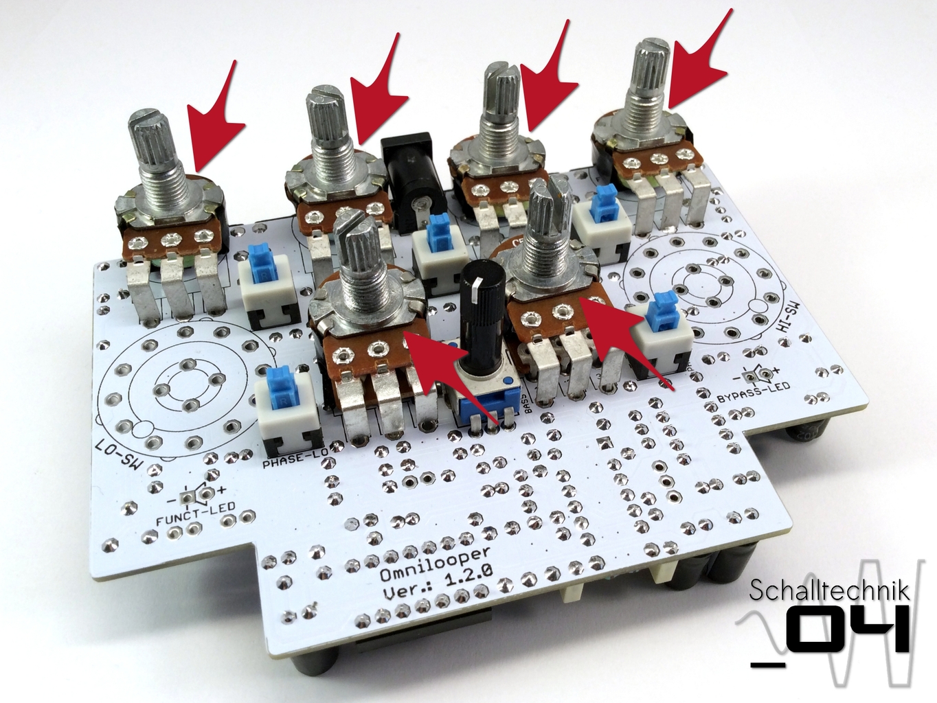 Insert angled pots … don’t solder, yet!
- Upper row: 4x 1x50kB (lin.)
- Lower row: 2x 2x50kC (rev. log.)
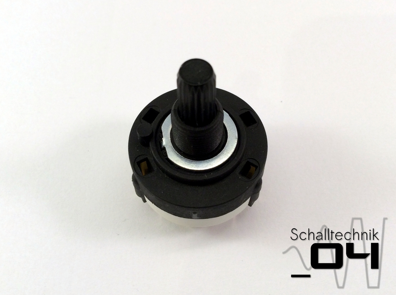
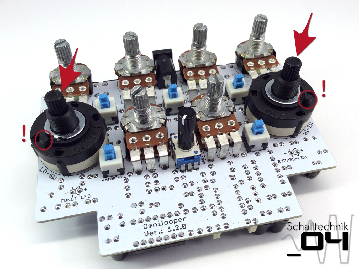 Insert rotary switch… don’t solder, yet!
Align correctly! Four positions are possible. BUT only one of those four positions fit to the enclosure. See picture!
 … turn the PCB and solder just one solder joint each.
Now it can be decided what the function of the second footswitch will be. It can switch Send-Boost (set via the internal trim pot) OR Bassboost. In this build the switchable Bassboost is shown.
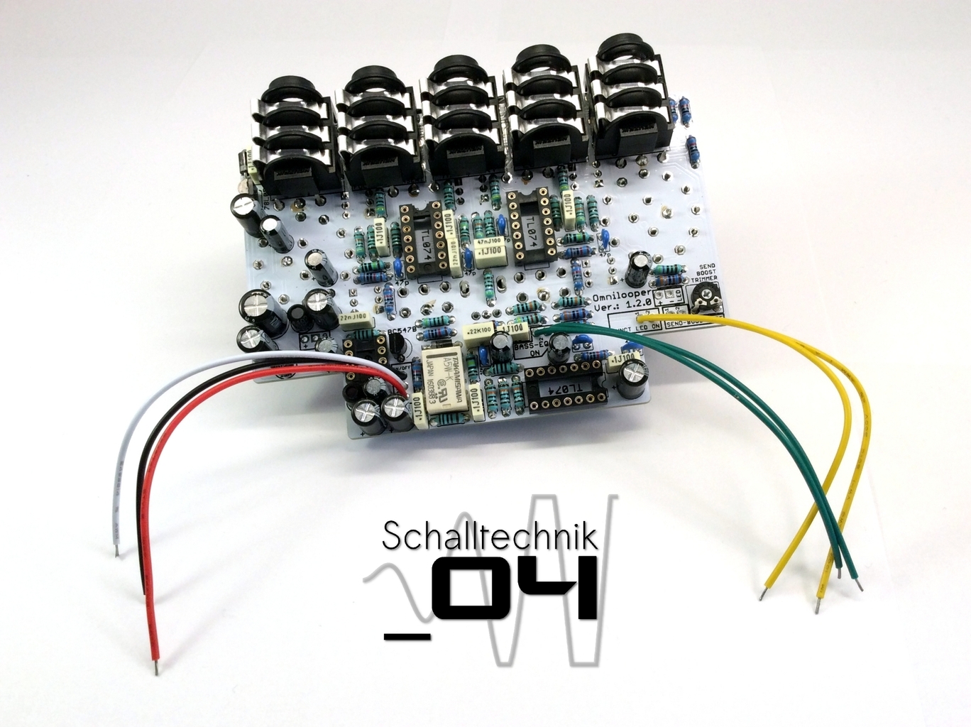
For the switchable Bassboost-Version the following cable need to be soldered to the PCB:
- ON/OFF-Port:
- PIN1: red
- PIN2: white
- PIN3: black
- BOOST-LED-ON-Port
- PIN1: yellow
- PIN2: yellow
- BASSBOOST-ON-Port
- PIN1: green
- PIN2: green
- SEND-BOOST-OFF-Port:
- PIN1: open (no cable)
- PIN2: open (no cable)
For the switchable SEND-Boost-Version the following cable need to be soldered to the PCB:
- ON/OFF-Port:
- PIN1: red
- PIN2: white
- PIN3: black
- BOOST-LED-ON-Port
- PIN1: yellow
- PIN2: yellow
- BASSBOOST-ON-Port
- PIN1: connected to: PIN2
- SEND-BOOST-OFF-Port:
- PIN1: green
- PIN2: green