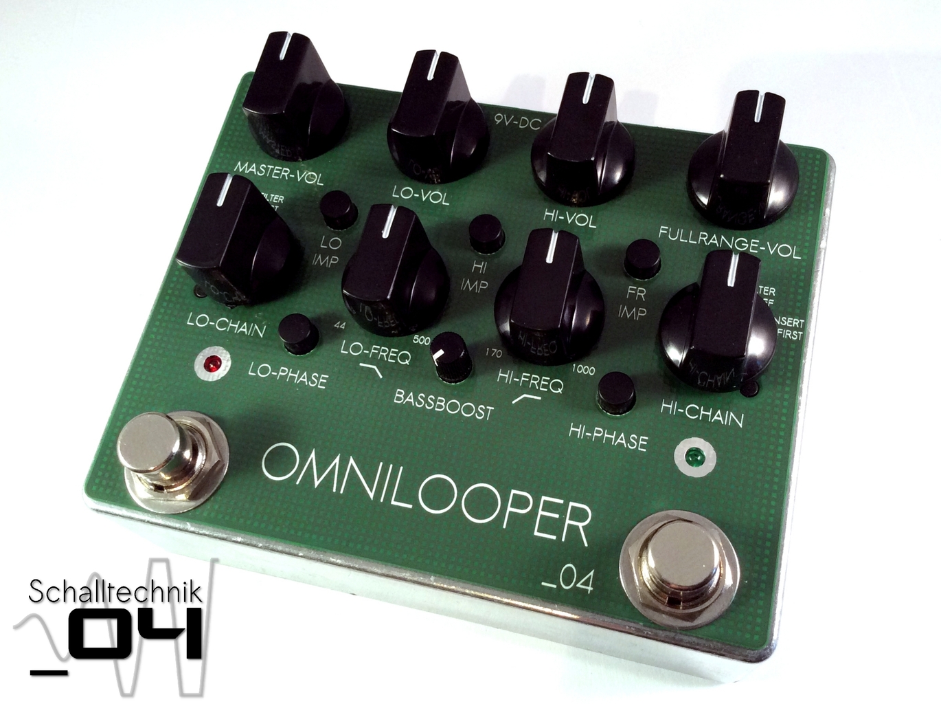
Assembly
Contents
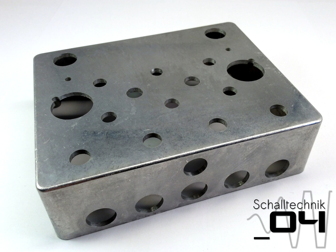
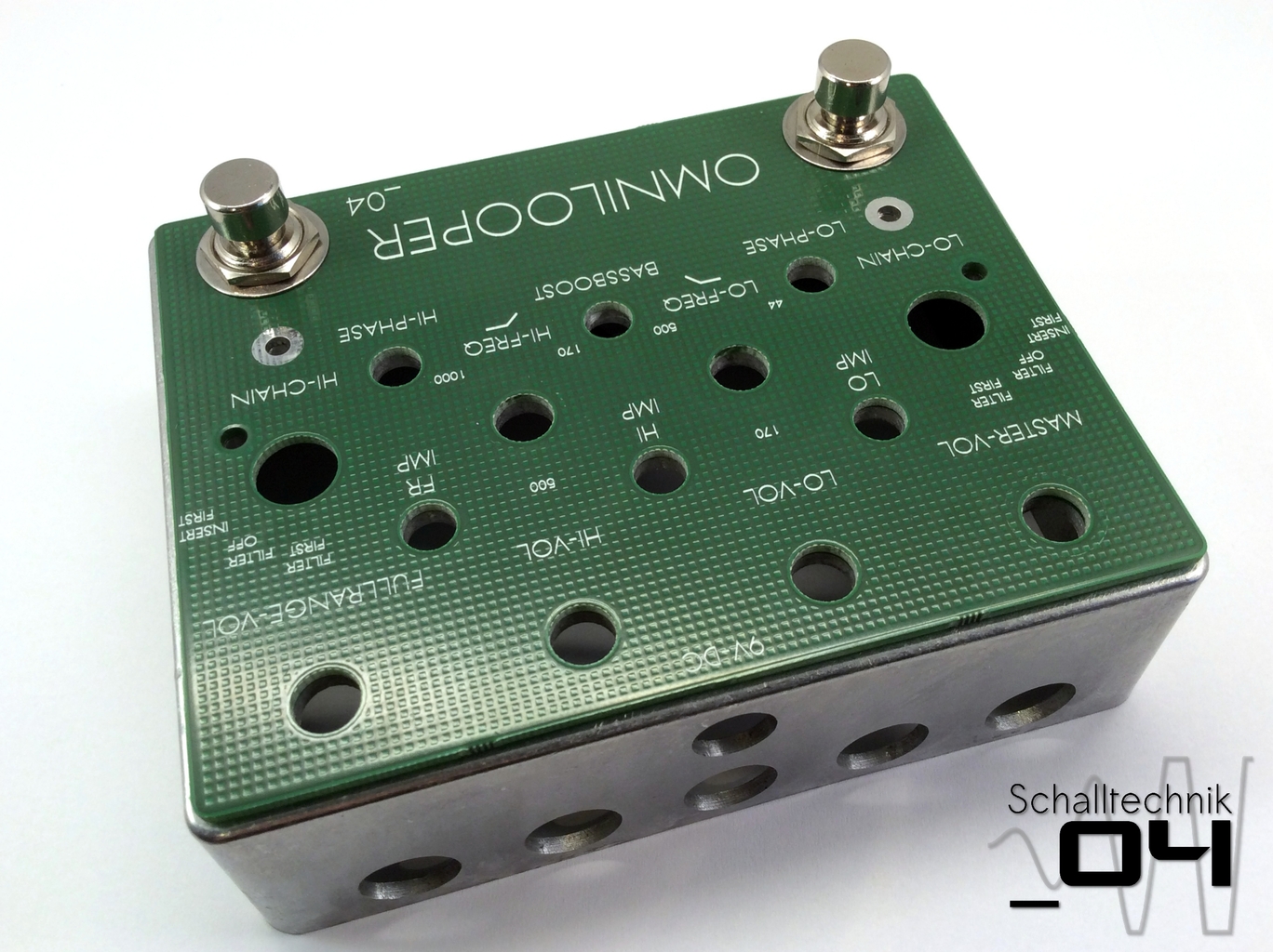
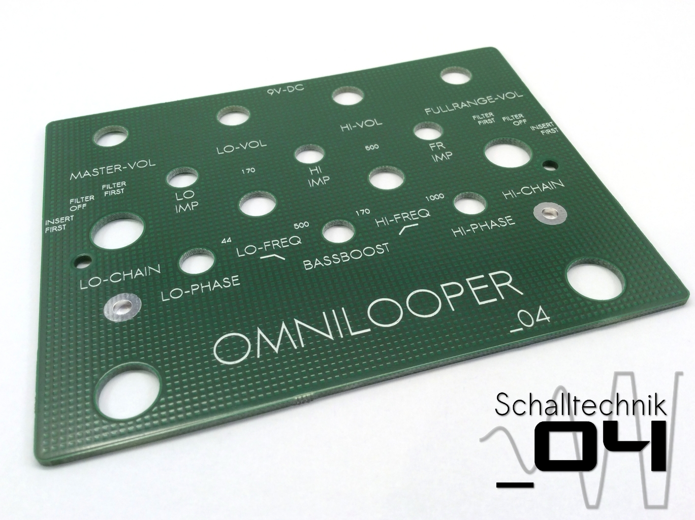 Take – if bought – the front-PCB and put it onto the predrilled enclosure.
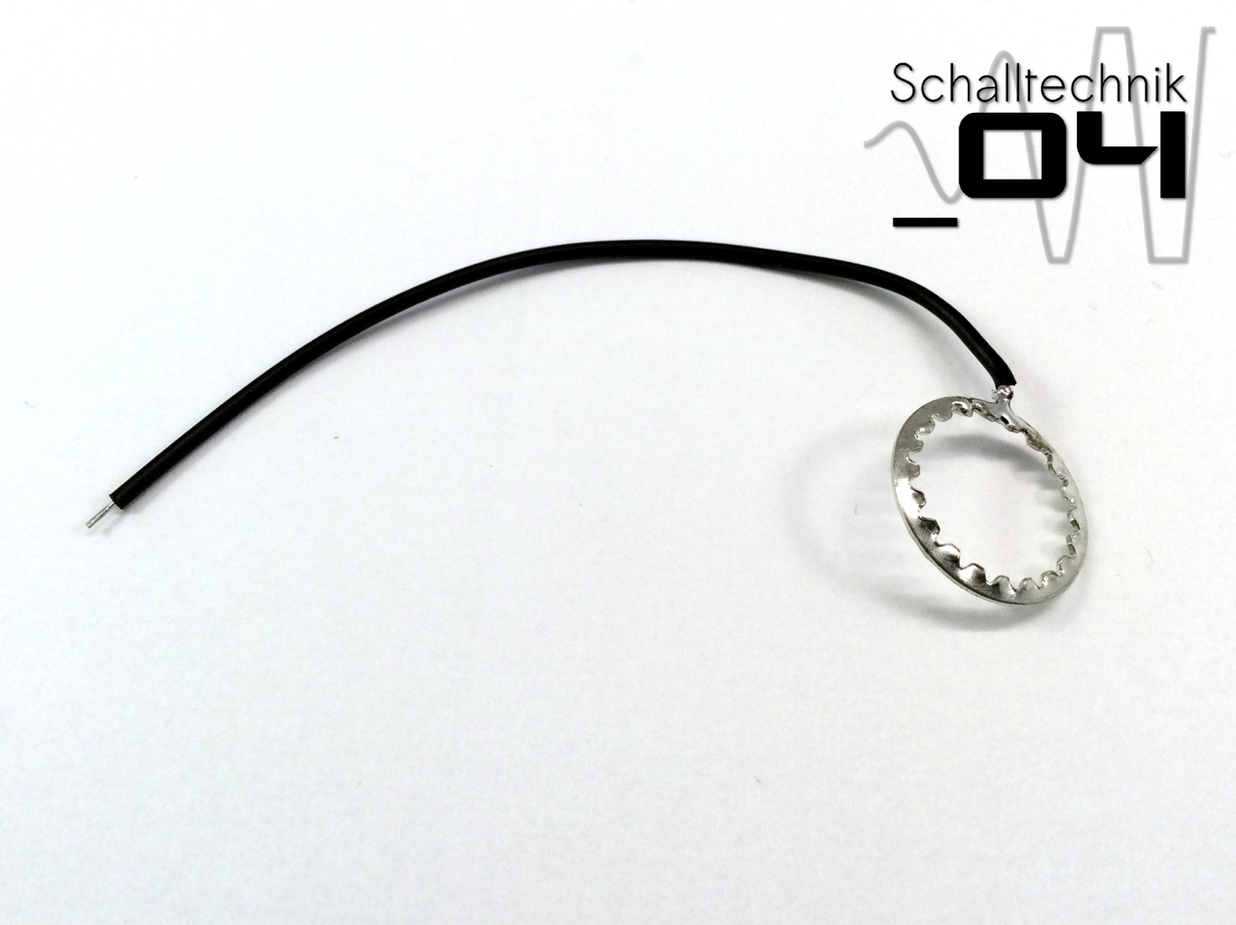 Solder a black cable to one of the two tooth washers (from the footswitches). It will be used for grounding the enclosure.
About shielding:
If we ground the enclosure it will act like a shield. Ungrounded the shielding effect is much smaller.
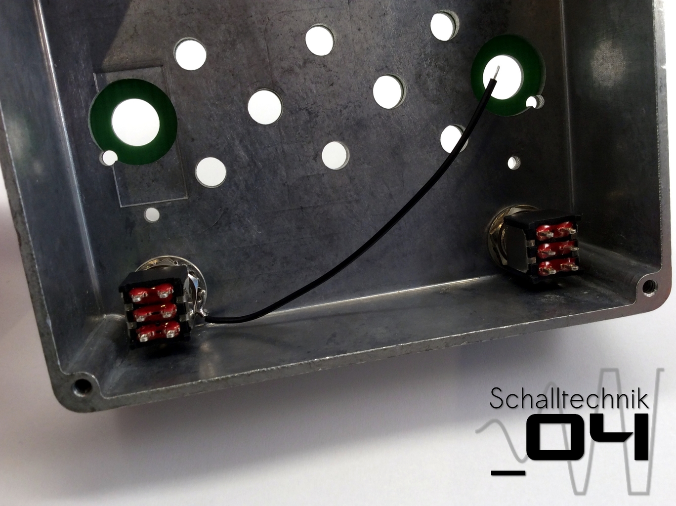 Now mount the foot-switches with the teeth washers and metalwasher (and the front pcb). The left footswich (bypass – ON/OFF) gets the teeth washer with the soldered on cable.
If the enclosure was painted, the area arround the teeth washer needs to be free of insulating paint.
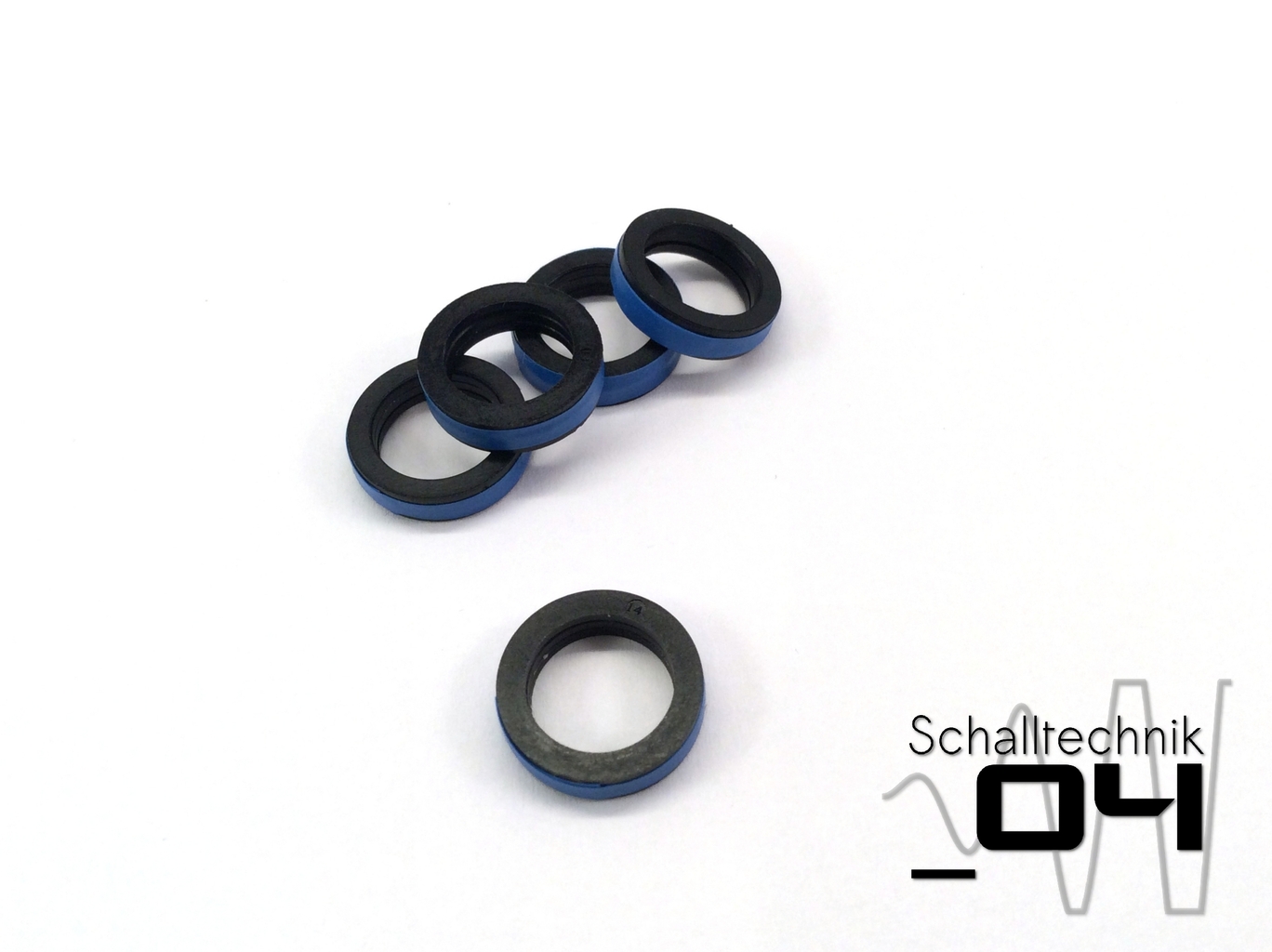 Use tape or super glue to fix three washers together. (they come with the jacks)…
 …then use super glue to glue the washers to the jacks.
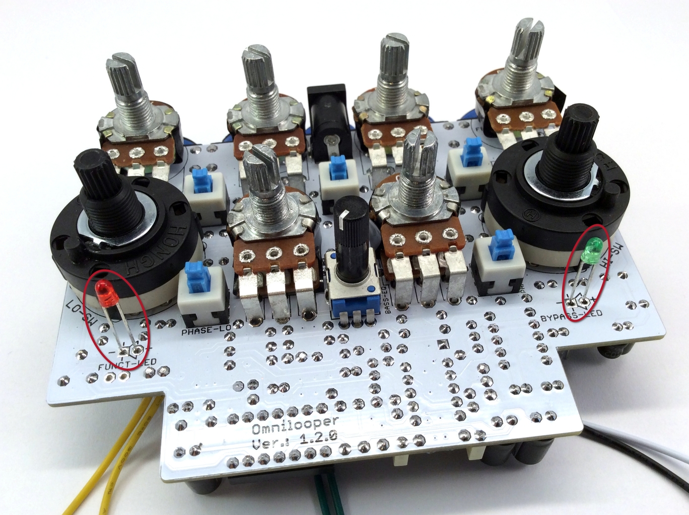 Insert the led. Don’t solder, yet! Align correctly!
- long leg: +
- short leg: –
If not already happened, remove the nuts and the teeth washers from the rotary switches!
 Insert the PCB completely into the enclosure. It is crucial to remain calm, it may take some attempts to get it right!
The rotary switches are installed correct, if the small plastic pins of the switches slightly stick out of the front of the enclosure!
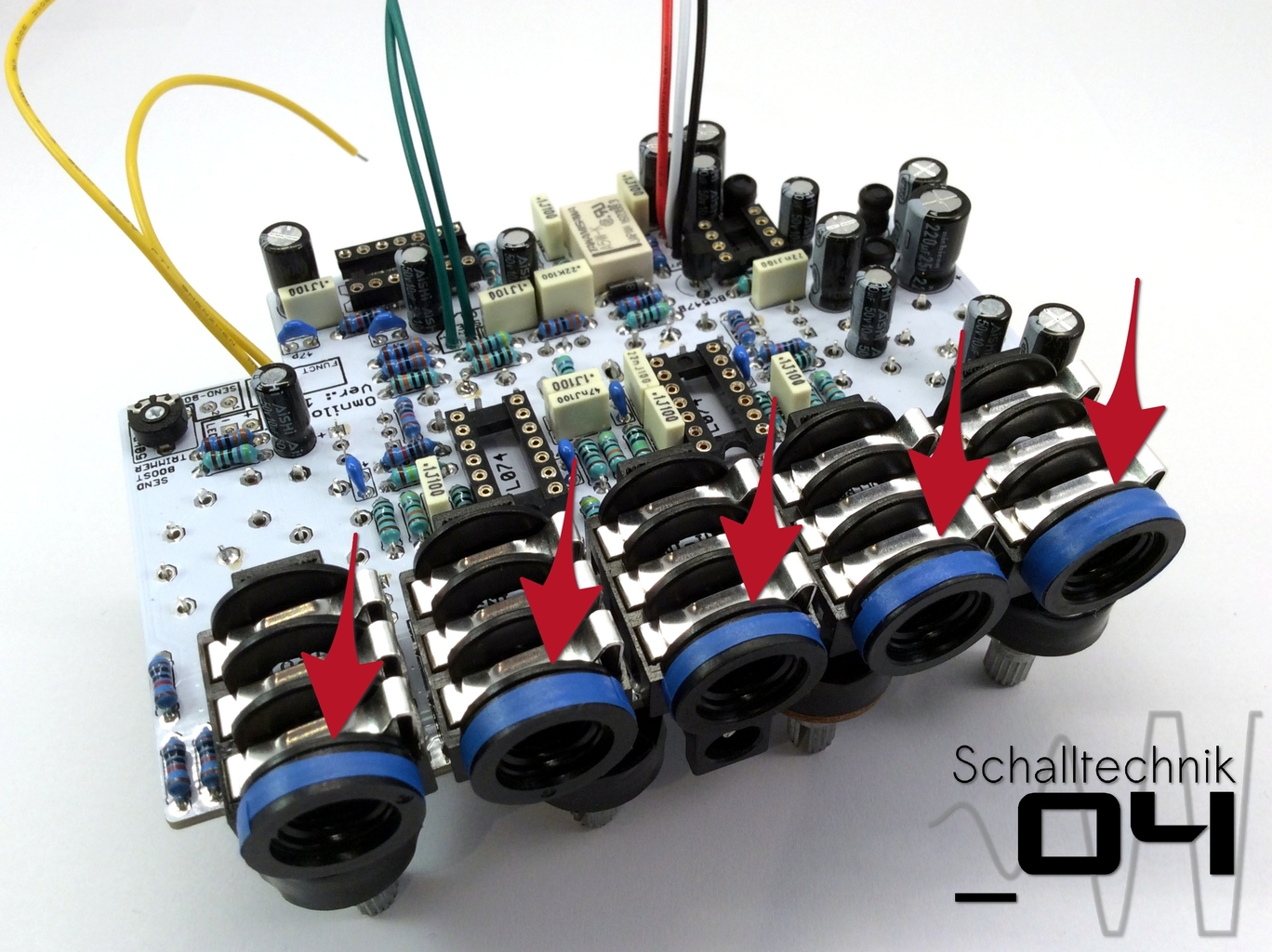
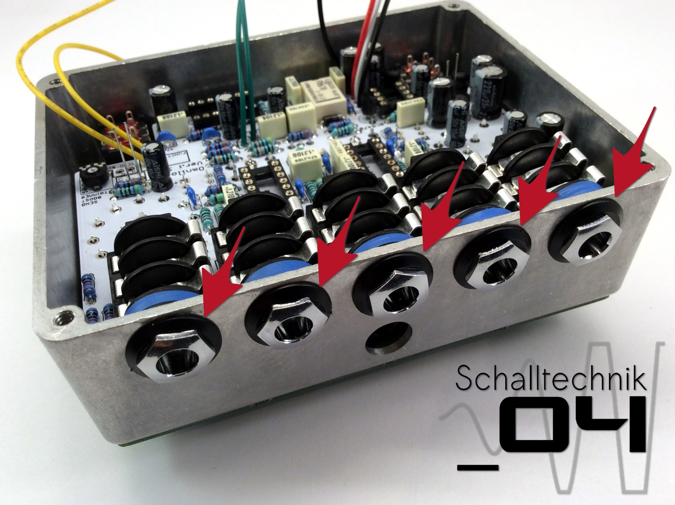
If all pots and switch fit, the ferrules (nuts) of the 1/4″-Jacks can be screwed to the enclosure.
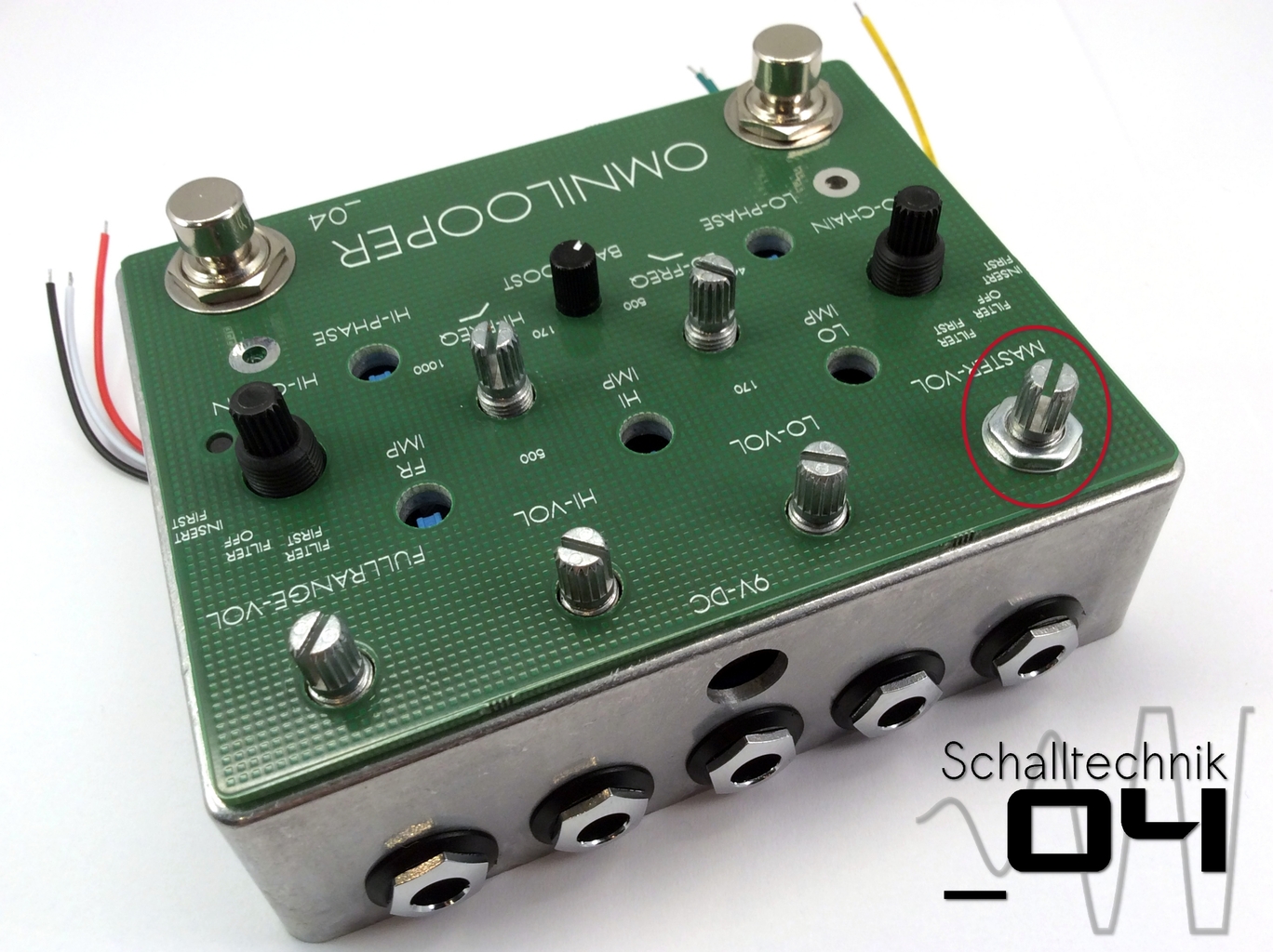
IMPORTANT!!
The pots and switches were just soldered to the PCB with one joint each. Now those parts need to be aligned perfectly to the enclosure/PCB, so the stress on the PCB gets minimized.
To do that: reheat the single set solder joint on each pot (one after the other) while pulling the shaft up and therefore the whole pot against the inner side of the enclosure front.
 Tighten the nut of the corresponding pot.
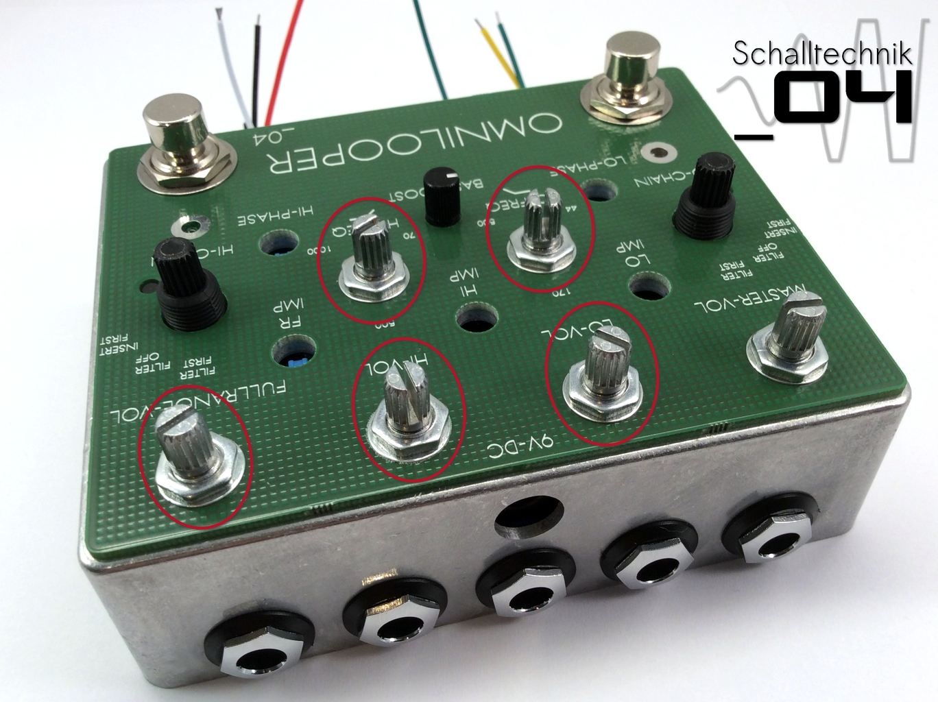 Repeat with the other pots
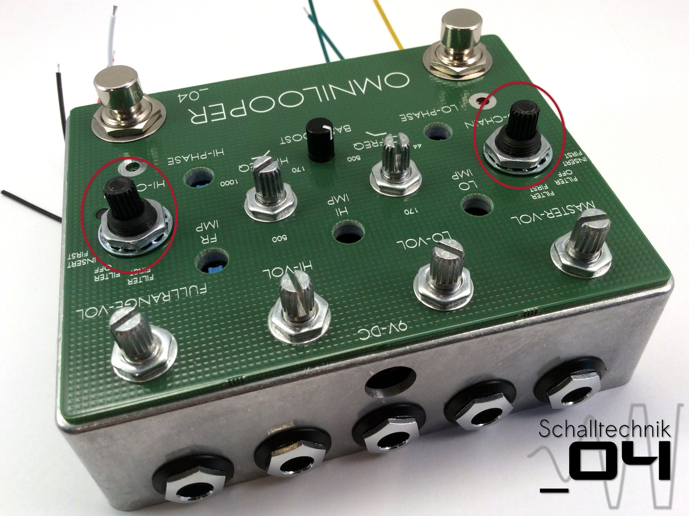
At last screw the nuts to the rotary switches. Tighten only slightly(!)
Add the caps of the switches. Then by reheating the already set solder joints try to fit the switch to the enclosure.
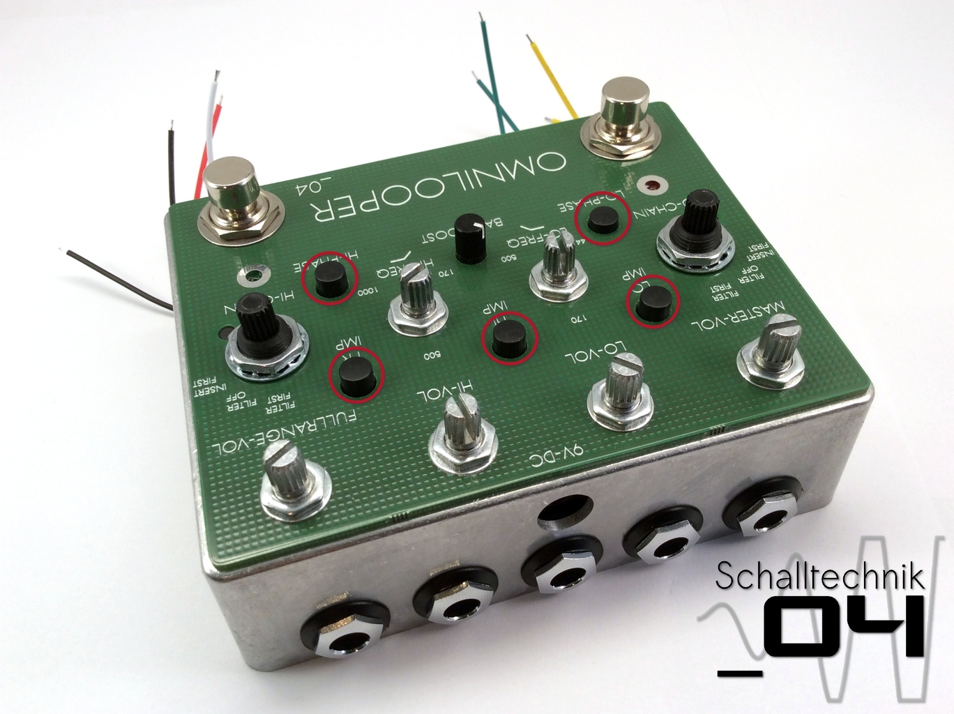
 Solder the LEDs to the PCB.
 Now you can solder all the other missing solder joints of the pots, switches.
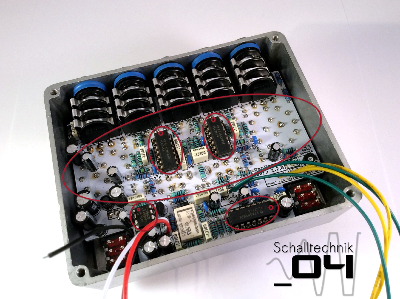
Next: Insert 3x TL074, 1x TC7662B. Align correctly!
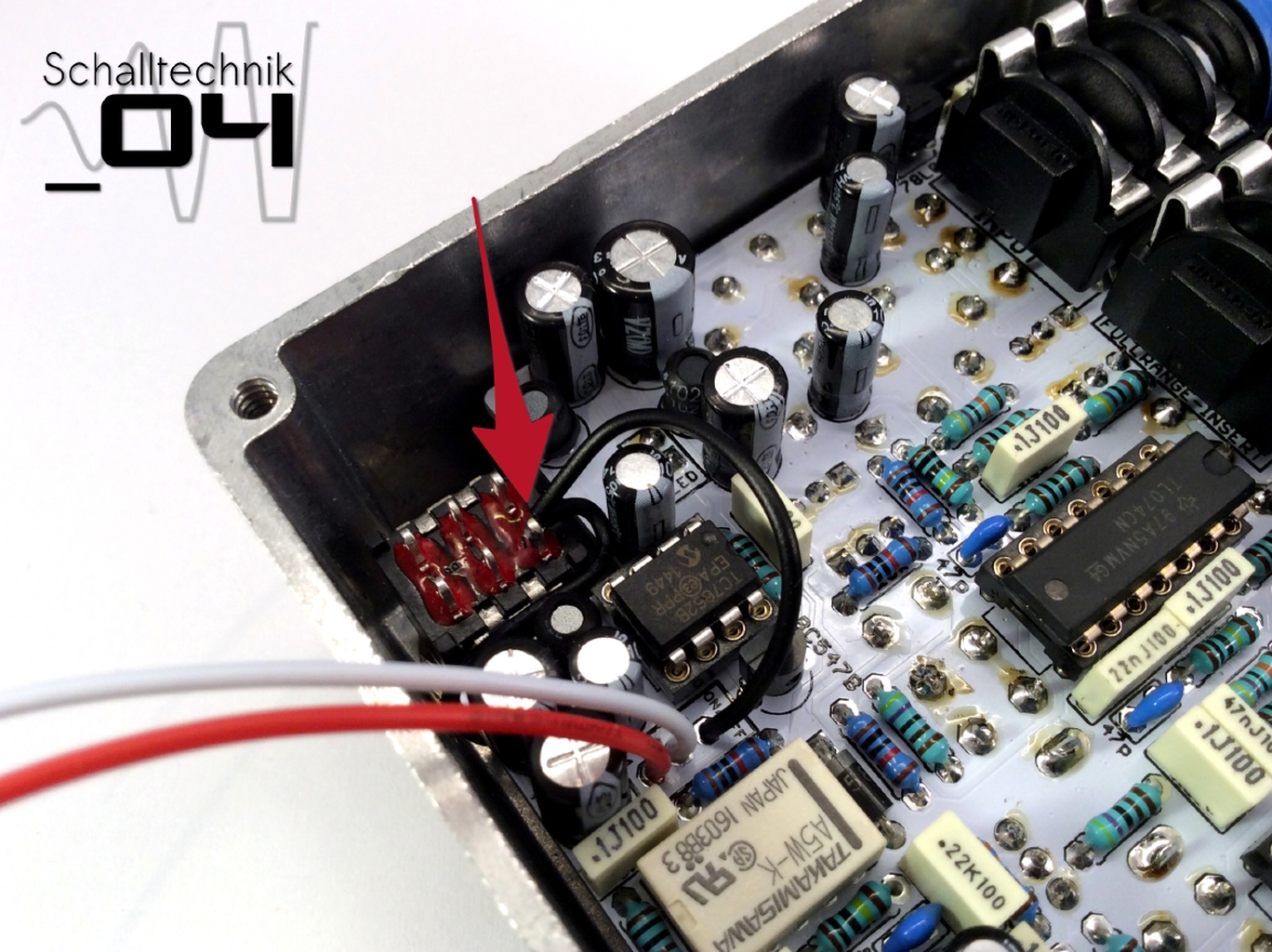 Solder the black cable (from the teeth washer) together with the cable vom “ON/OFF”-Port Pin:3 (also: black) to the outer pin on the footswitch.
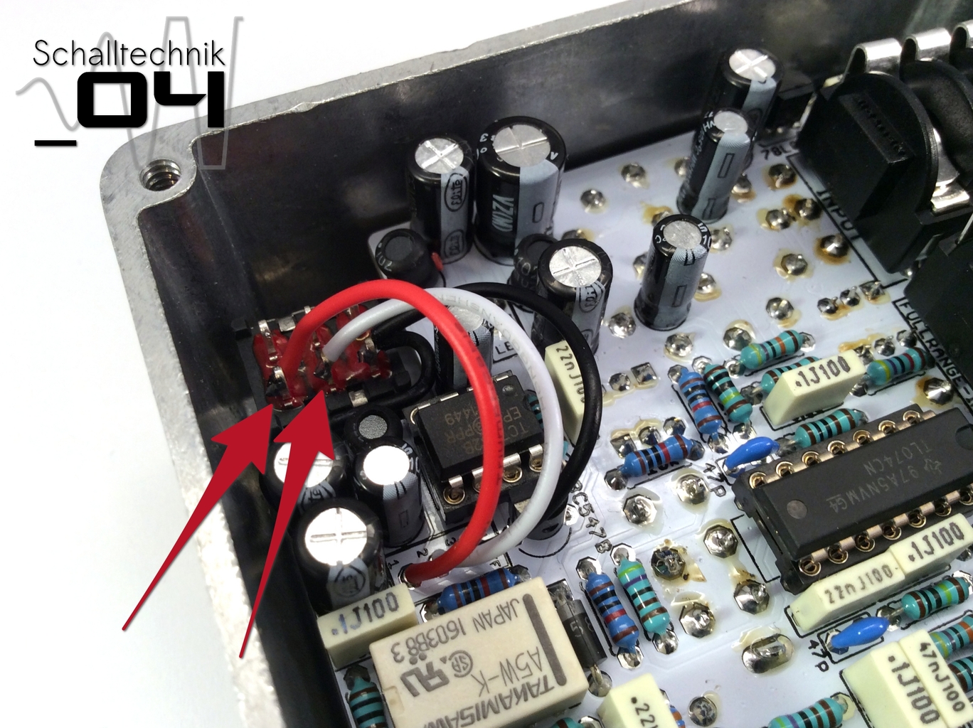 Solder the white (middle pin) and the red cable (the other outer pin) to the footswitch. Do no mix it up!
 Solder the two yellow cables (LED) as shown to the other footswitch.
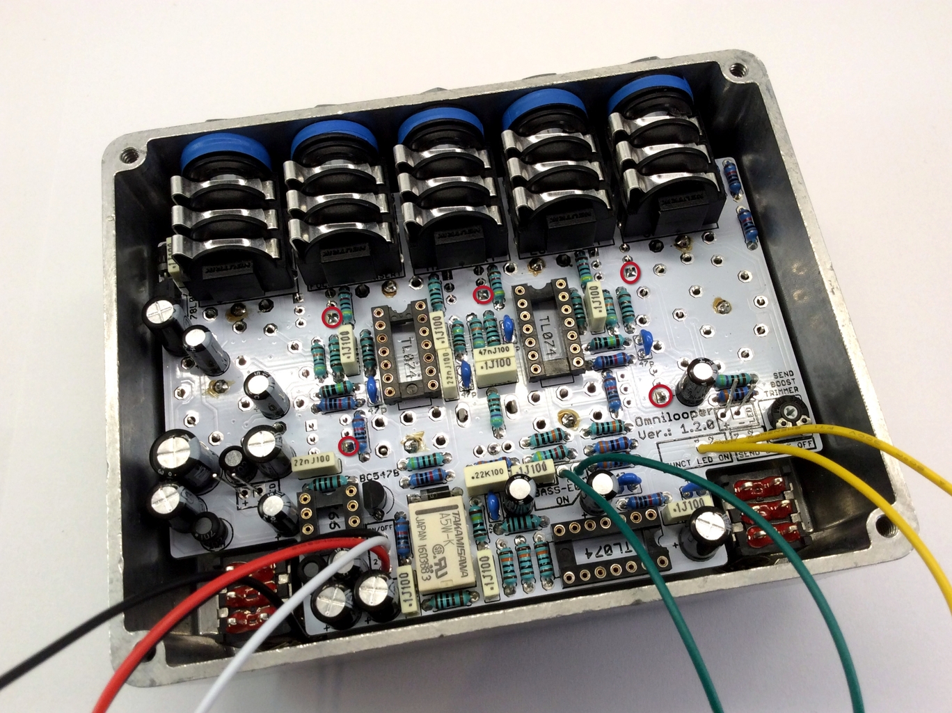
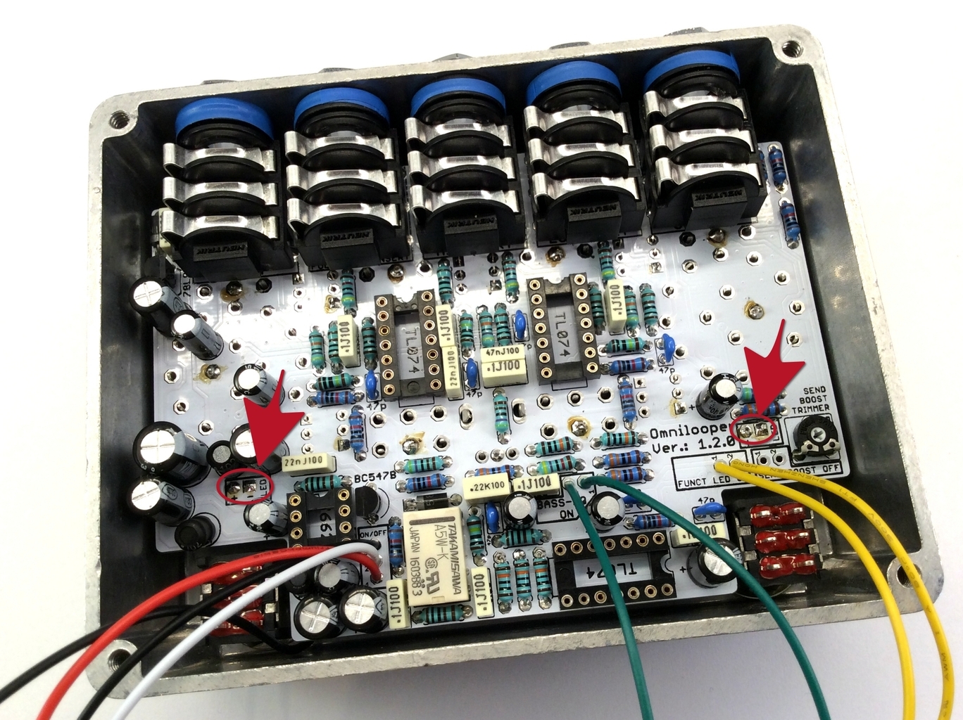
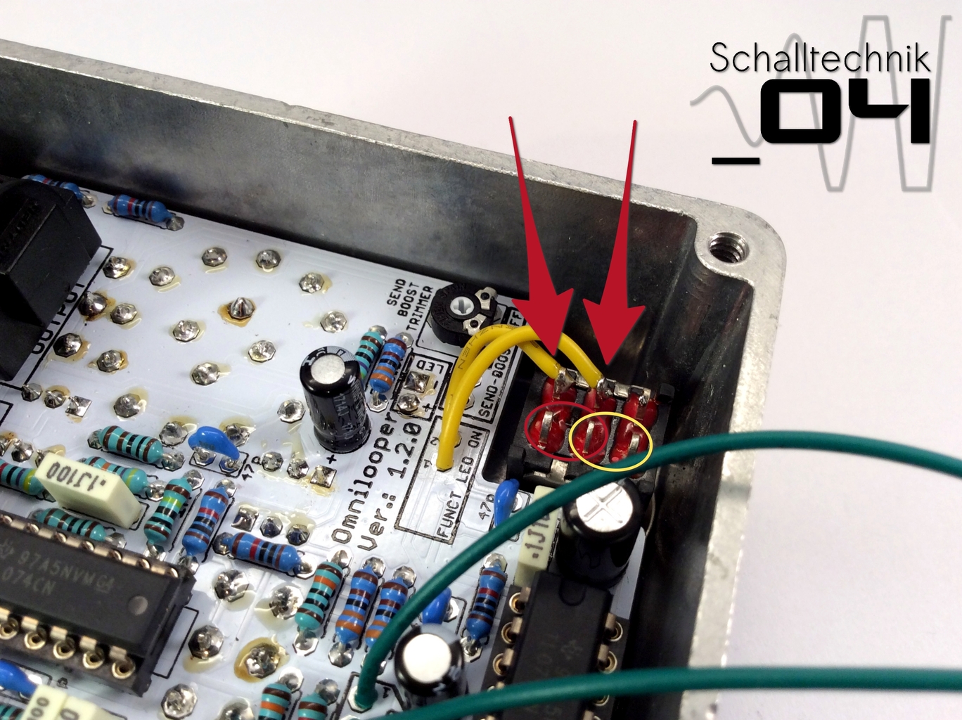
Now the wiring of the Bassboost-Ports/Send-Boost-Ports (depending of the Version you choose) gets done:
- switchable Bassboost: cables to the PINs within the red circle
- switchable Send-Boost: cables to the PINs within the yellow circle
It is not possible to switch both functions at the same time! You got to choose one Version.
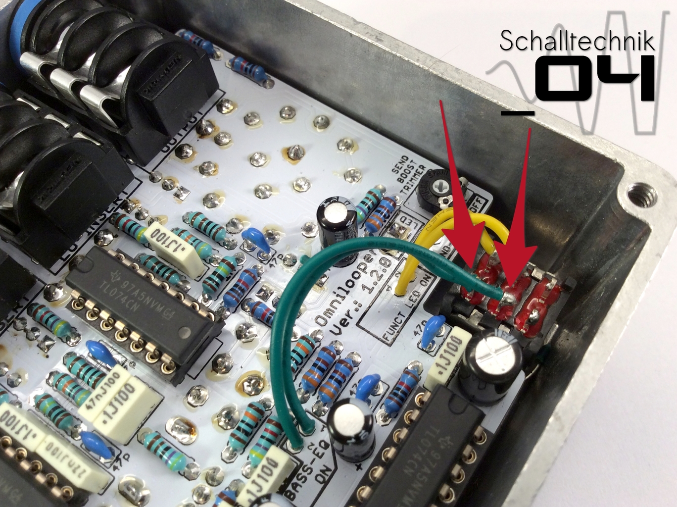 Version shown here: switchable Bassboost
 Now everything is done for some functional testing!

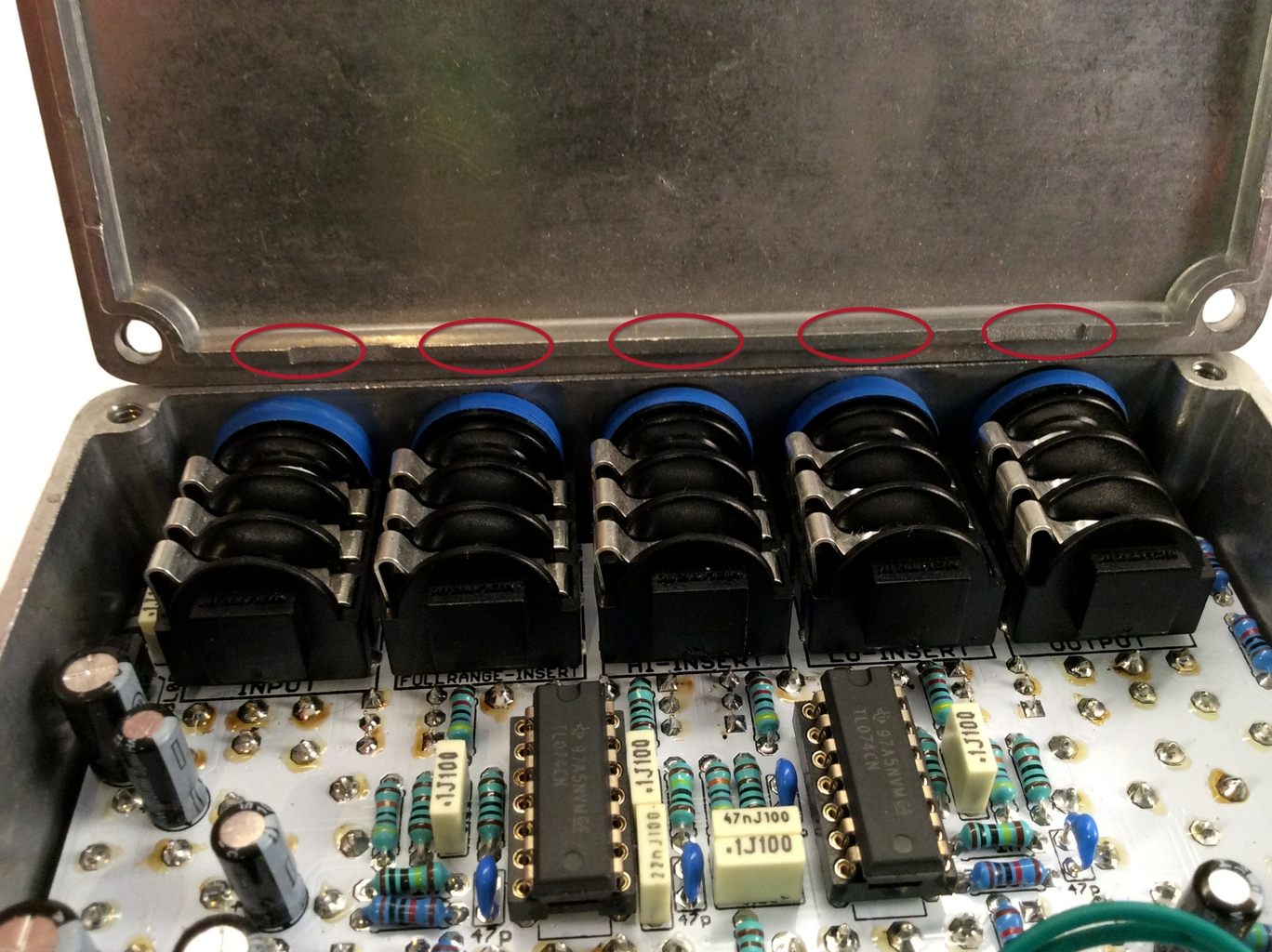 At very last. The lid needs some small modification.
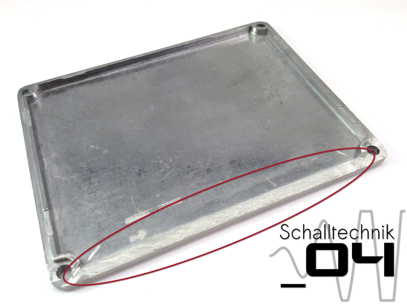 Here a small rotary tool with a metal cutting disk was used to remove to part. A normal metal file will also do the job.
Hint: If needed a small hole can be drilled in order to be able to set the SEND-BOOST-TRIMMER without removing the lid.
If not needed, set the “SEND-BOOST-TRIMMER” to minimum (7 o’clock). In this setting the gain is 1. (same volume as input level)
Close the lid. Done!

Ready for full testing! Have fun!