PCB-assembly 2/2
Contents
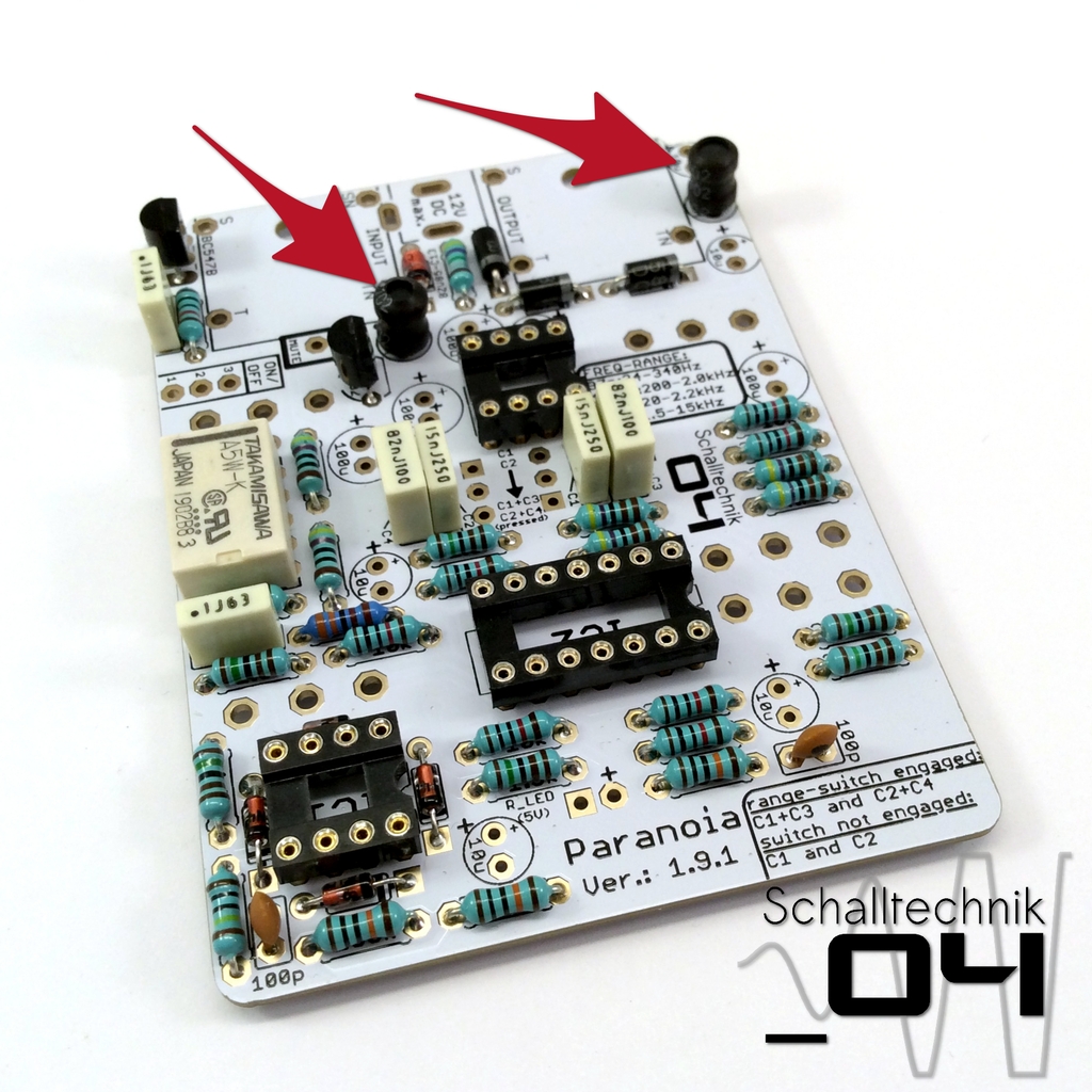
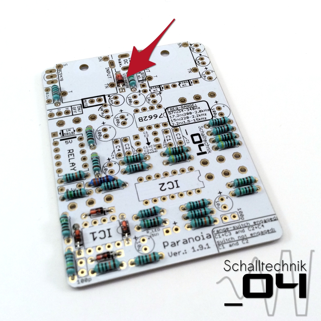 Insert 13V-1,3W zener diode (1x) and solder it. Align correctly!
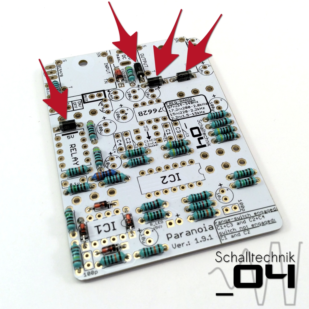 Insert 1N5818 diodes (4x) and solder them. Align correctly!
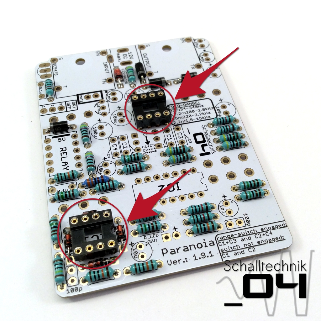 Insert the 8 Pin DIL-Sockets (2x) and solder them. Align correctly!
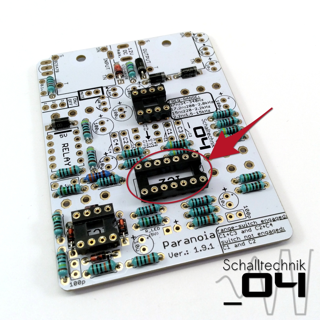 Insert the 14 Pin DIL-Socket (1x) and solder it. Align correctly!
 Insert 100pF capacitors (7x) and solder them.
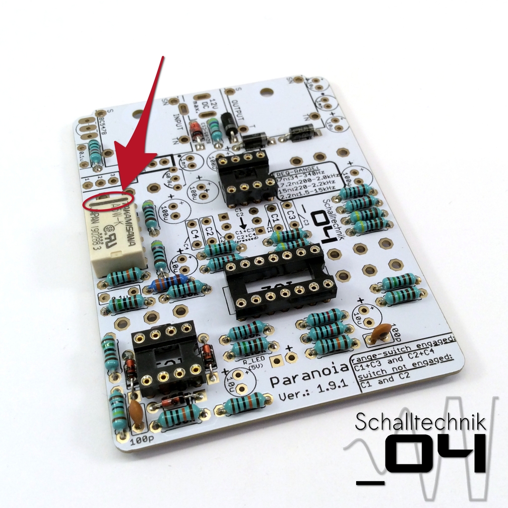 Insert relay (1x) and solder it. Align correctly! “bar to bar”
Note: Please check if you got the correct relay.
The correct types are: FRT5 DC5V, Takamisawa A-5W-K or Zettler AT850-5!
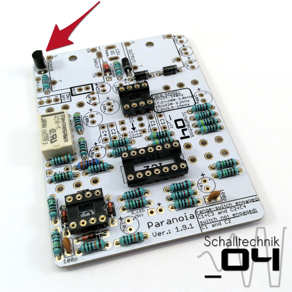 Insert BC547B transistor (1x) and solder it. Align correctly!
ATTENTION! DO NOT confuse it with 78L05!
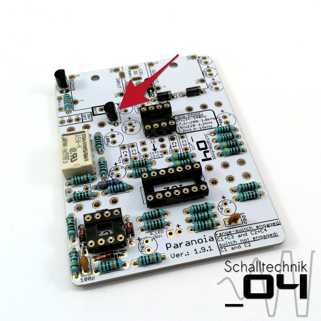 Insert 78L05 (XX78L05XXX) (1x) and solder it. Align correctly!
ATTENTION! DO NOT confuse it with BC547B!
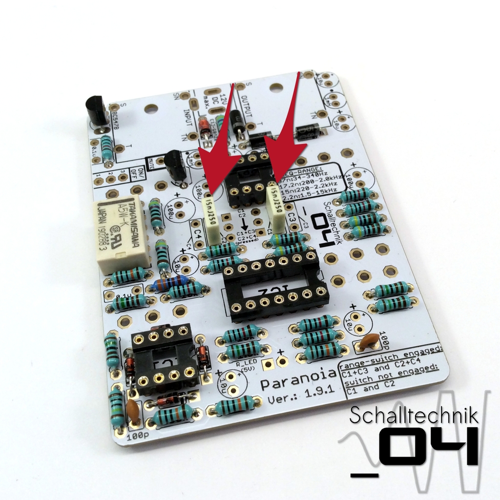 Please populate C1 und C2 as needed.
- low/mid -> C1, C2 = 15nF; C3, C4=82nF
- mid/high -> C1, C2 = 2,2nF; C3, C4=15nF
The picture shows the low/mid configuration.
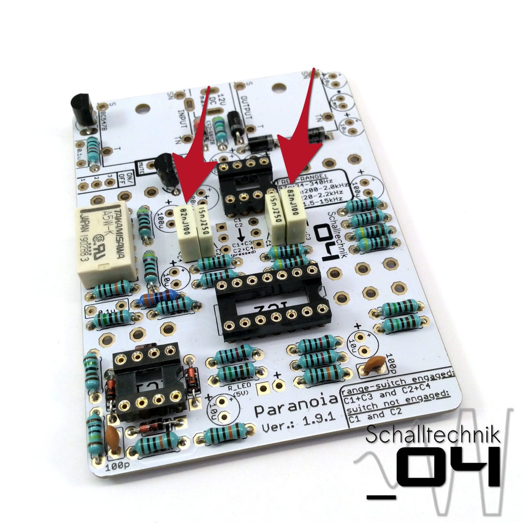 Please populate C3 und C4 as needed. Values see above
The picture shows the low/mid configuration.
 Insert 100nF (.1X###) capacitors (2x) and solder them.
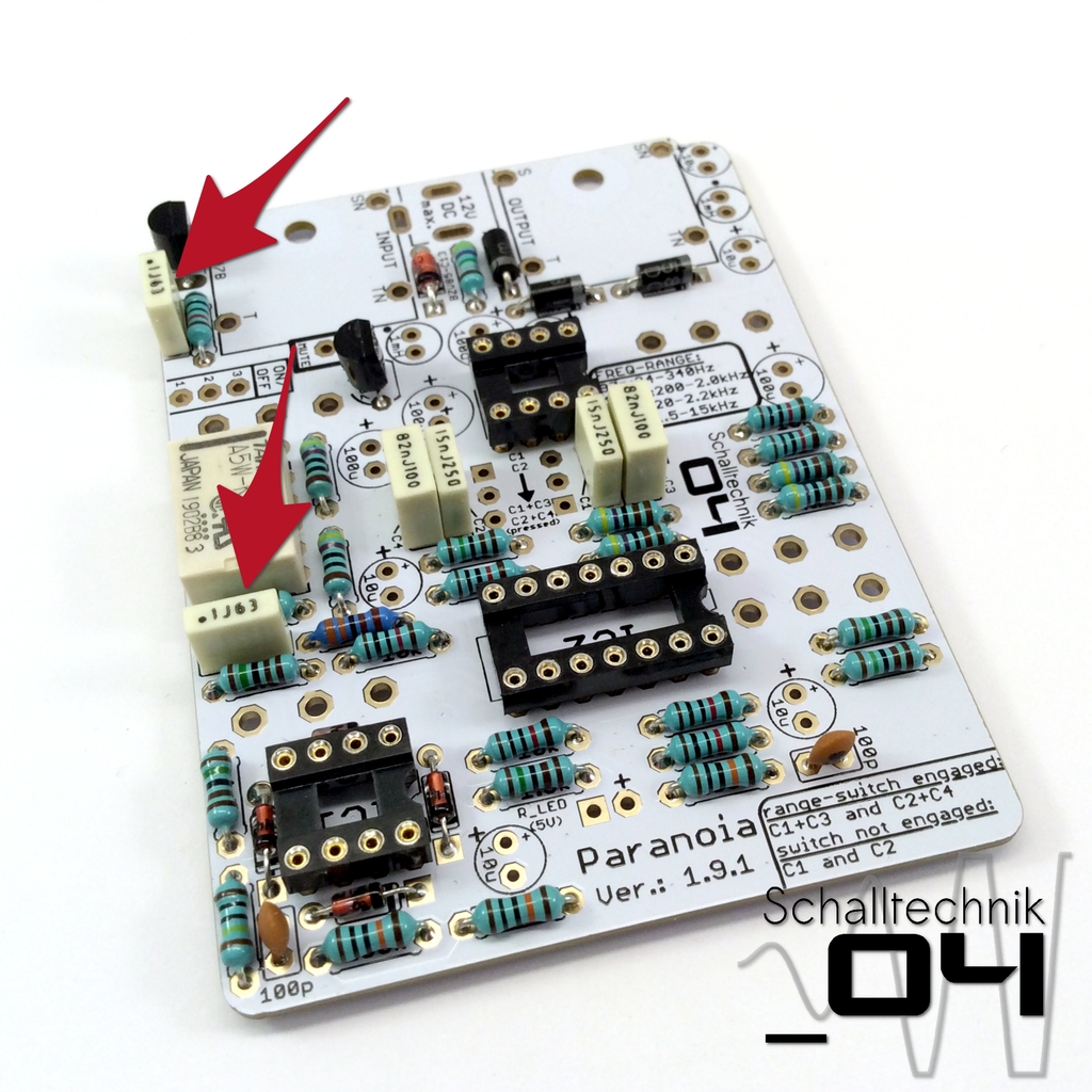
 Insert 1mH (102) Inductors (2x) and solder them. Align correctly! “Dot to Dot”
The pads are quite near to each other. Don’t accidentally bridge them!
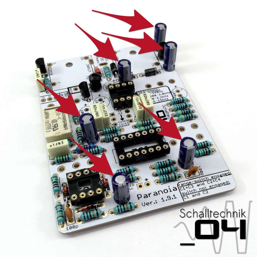 Insert 10µF capacitors (6x) and solder them. Align correctly!
The pads are quite near to each other. Don’t accidentally bridge them!
 Insert 100µF capacitors (4x) and solder them. Align correctly!