Assembly
Contents
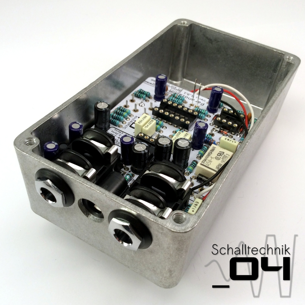 Insert the PCB completely into the enclosure. It is crucial to remain calm, it may take some attempts to get it right!
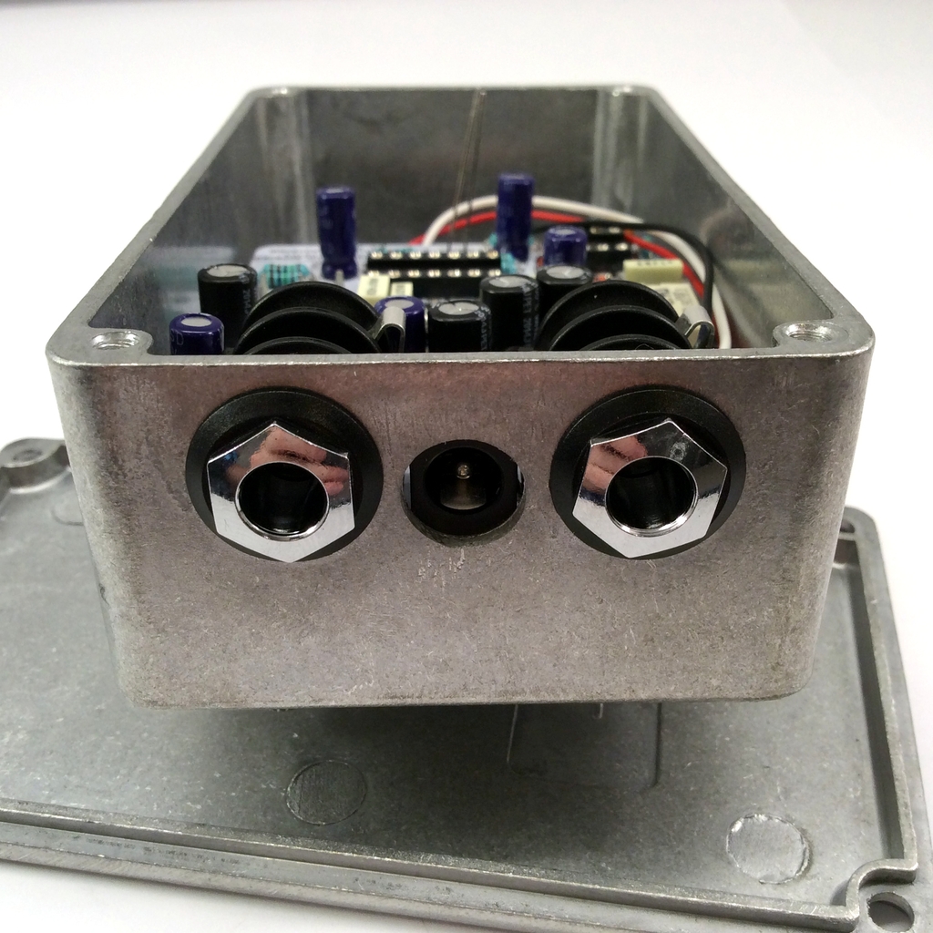 If all pots and the switch fit, the ferrules (nuts) of the 1/4″-Jacks can be screwed to the enclosure. Take care that the DC-IN jack is centered.
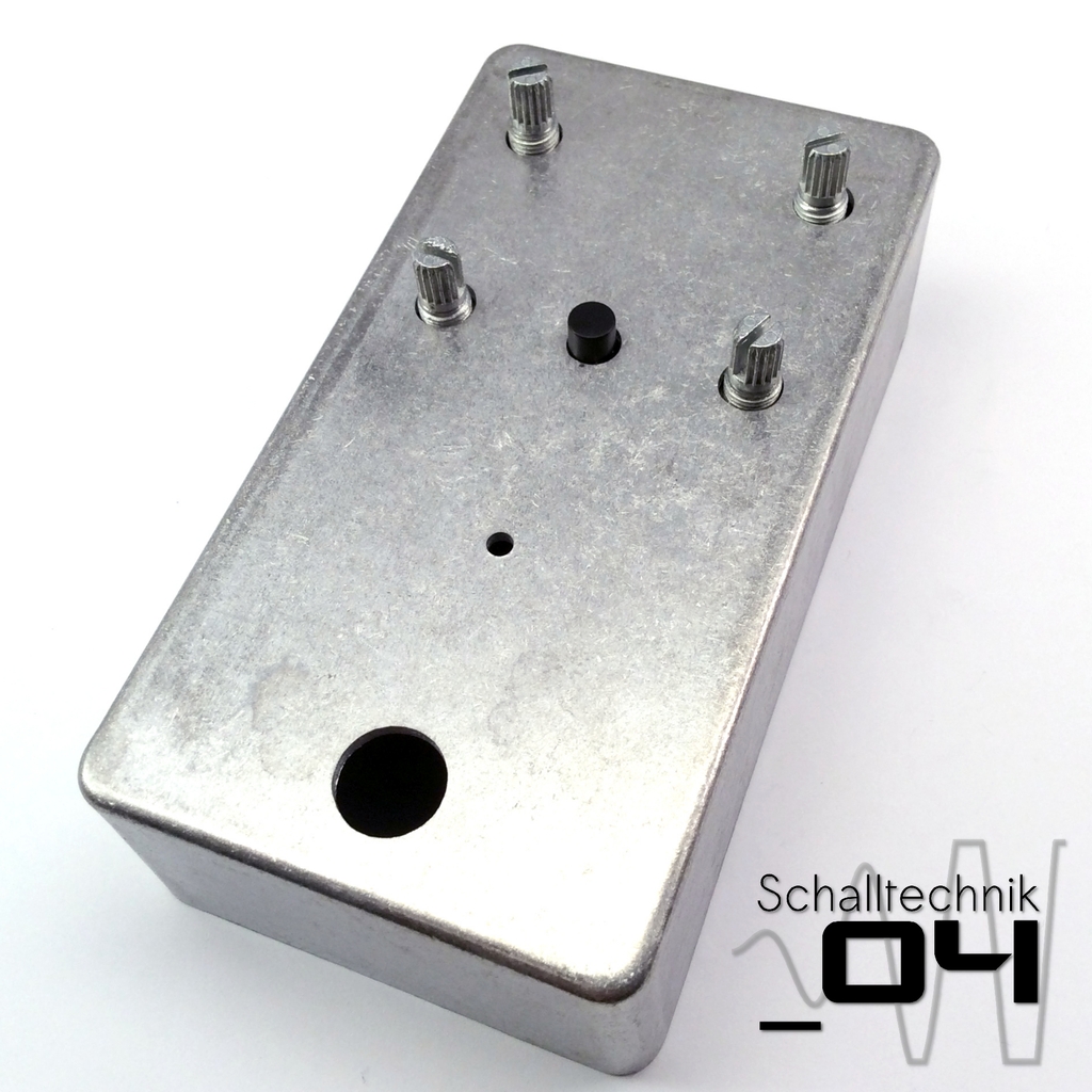
 Take – if bought – the front-PCB and put it onto the predrilled enclosure. Now mount the foot-switches with the teeth washers and metalwasher (and the front pcb).
Note – front-PCB: The front-PCB has different artworks one each side. Use the side which fits to your configuration.
Note – coating: If the enclosure was painted, the area arround the teeth washer needs to be free of insulating paint.

IMPORTANT!!
The pots and switches were just soldered to the PCB with one joint each. Now those parts need to be aligned perfectly to the enclosure/PCB, so the stress on the PCB gets minimized.
To do that: reheat the single set solder joint on each pot (one after the other) while pulling the shaft up and therefore the whole pot against the inner side of the enclosure front.
Then tighten the nut of the corresponding pot.
 Repeat with the other pots
 Put the LED though the front…
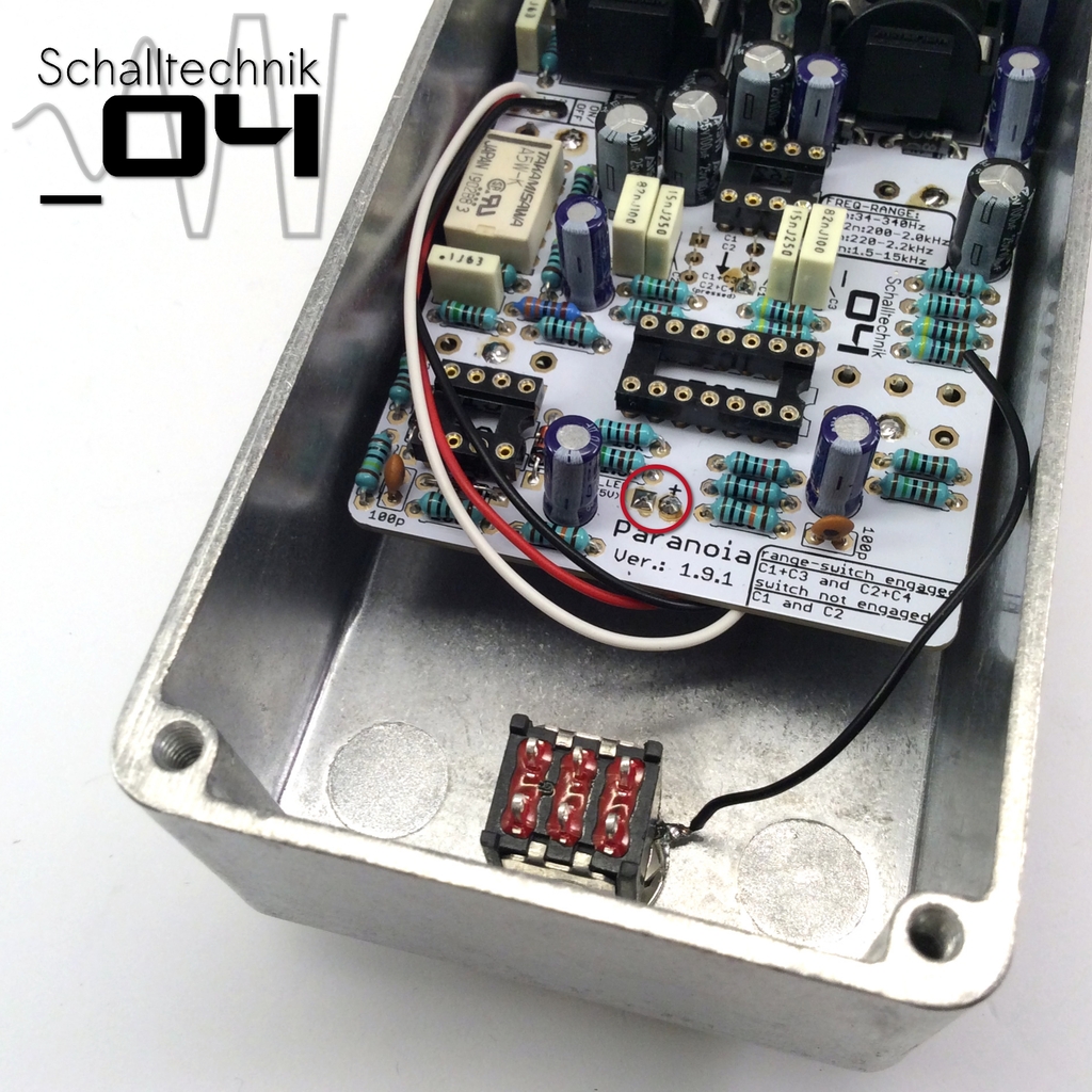 … an solder the LED to the PCB.
 If the switch isn’t a prefect fit (dragging). Reheating the already set solder joint and try to fit the switch to the enclosure.
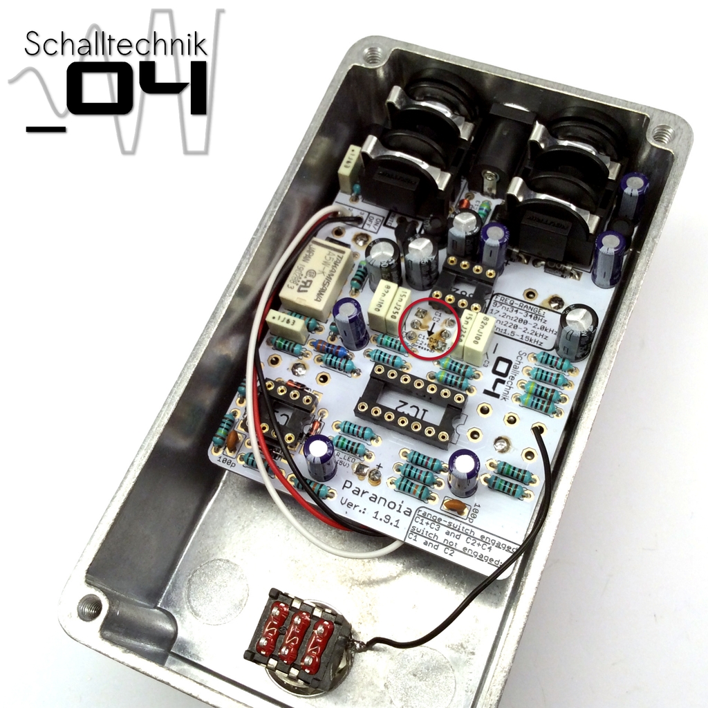 Then solder the other 5 solder joints of the switch.
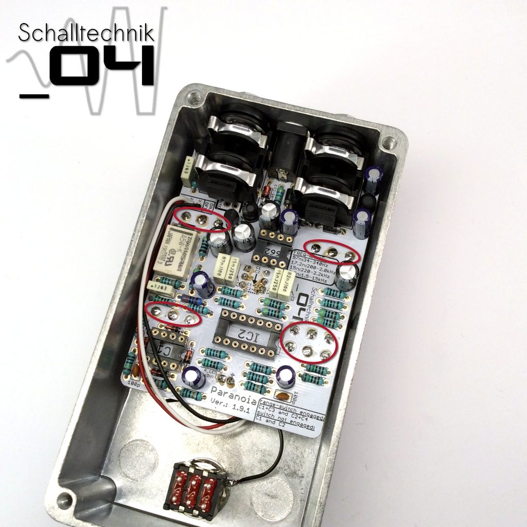 Now you can solder all the other missing solder joints of the pots.
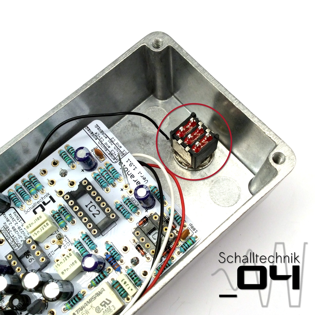
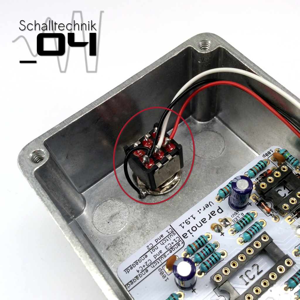 Solder the black cable (from the teeth washer) together with the cable vom “ON/OFF”-Port Pin:3 (also: black) to the outer pin on the footswitch.
Solder the white (middle pin) and the red cable (the other outer pin) to the footswitch. Do no mix it up!
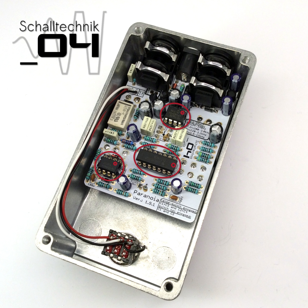 Insert 1x TC7662B (top), 1x TL074 (middle), 1x TL072 (bottom). Align correctly! Do no mix them up!
 Now everything is done for some functional testing!