Assembly Preparations
Contents
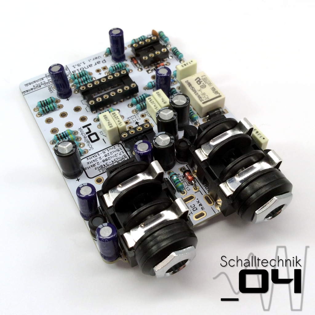
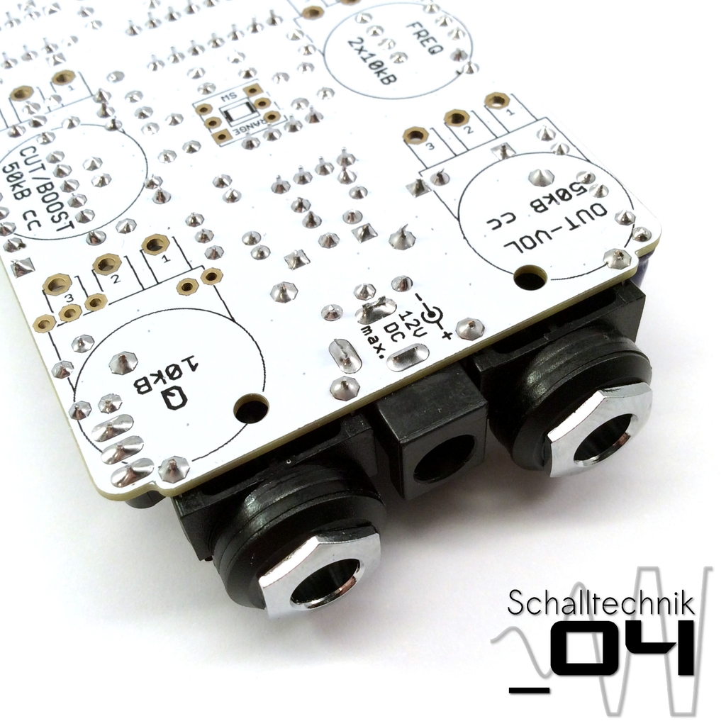
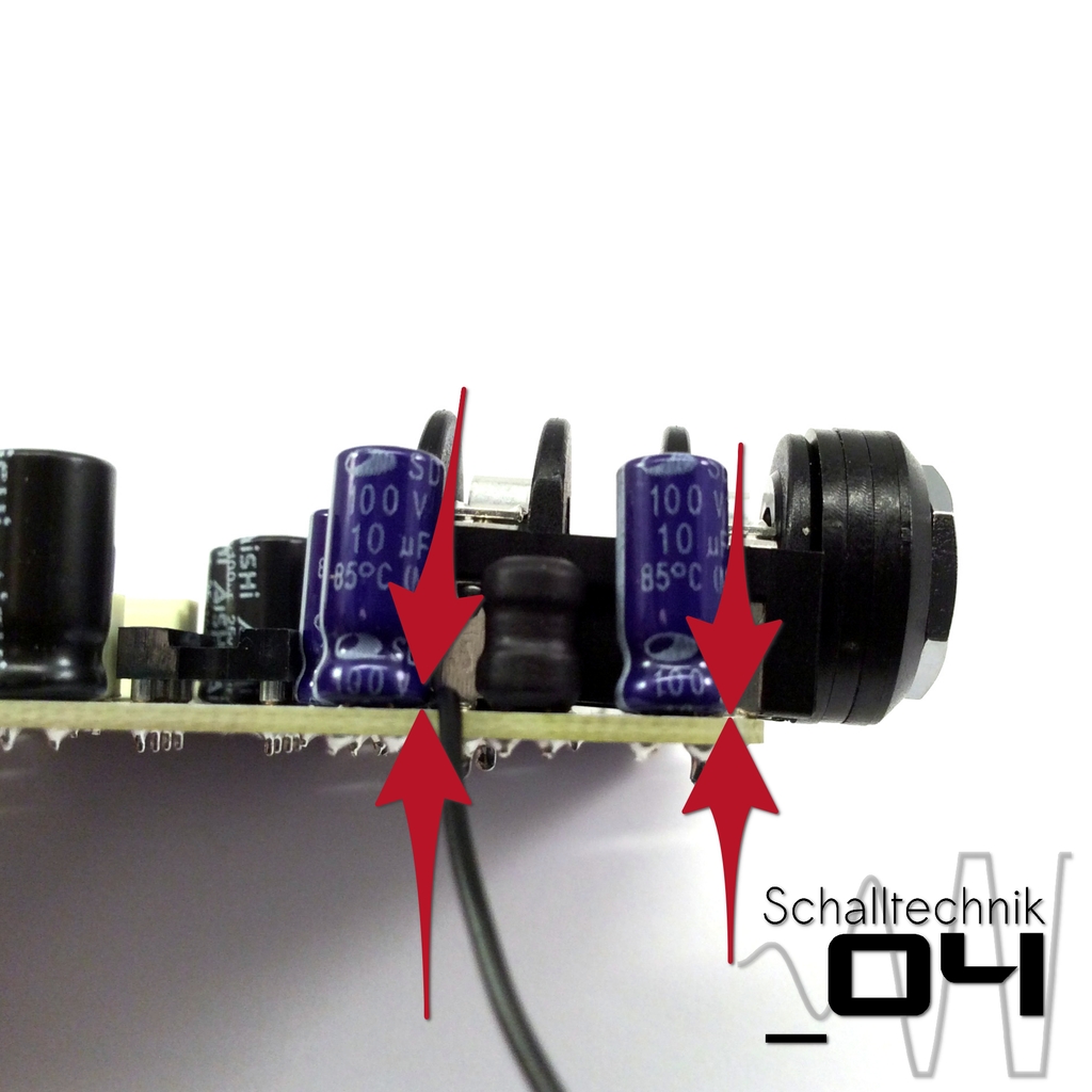 The 125B-enclosures aren’t rectangular, thus we need to mount the input- and outputjacks with a small angle. I use a piece of wire, which I put under the jacks (see in the pictures). Then I solder them.
The wire should be removed afterwards.
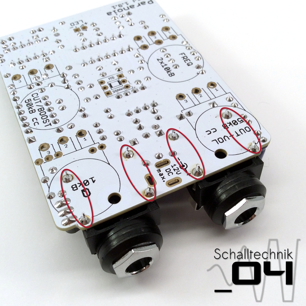 Shorten the ends of the 1/4″-jack…
 …reheat the solder joints.
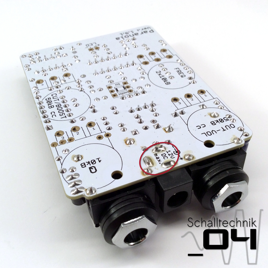
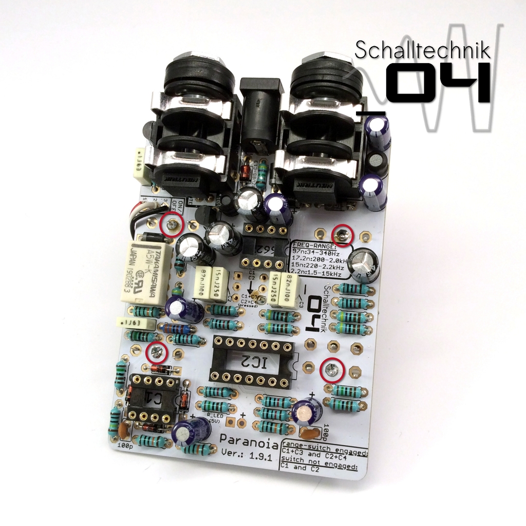
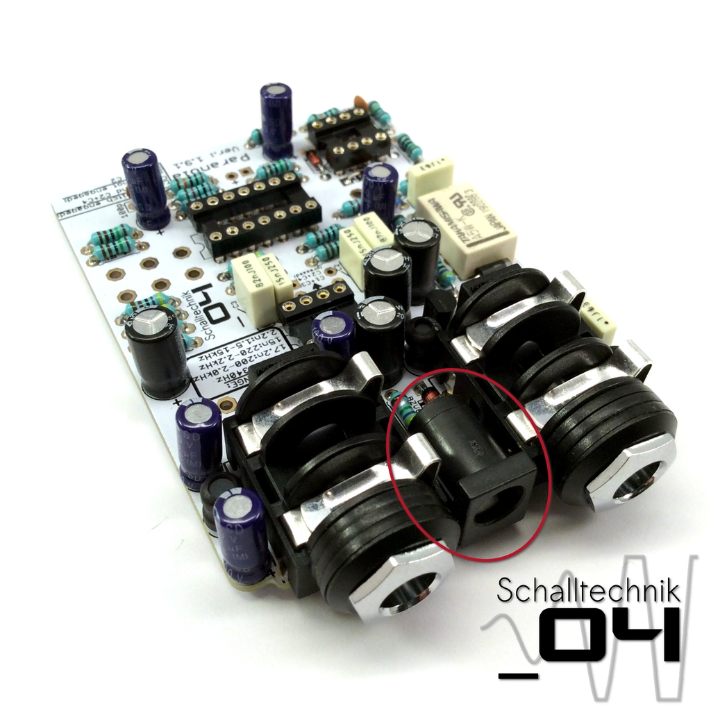 Insert and solder dc-in-jack to the PCB.
Take care that it is soldered in straight!
 Shorten the ends of the dc-in-jack, reheat the joints.
 Carefully clean the flux of those joints away and let them dry.
 Insert the DPDT-Switch, but (!) …
 … solder it just on one joint.
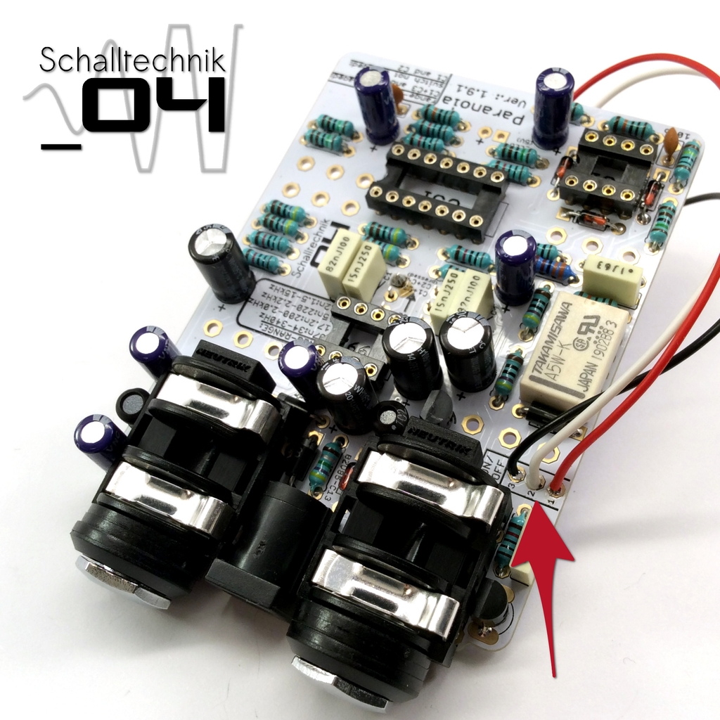 Solder wires to the “ON/OFF”-Port.
- PIN1: red
- PIN2: white
- PIN3: black (GND)
 Now we take the tooth washer which comes with the footswitch and solder a wire to it.
About shielding:
If we ground the enclosure it will act like a shild. Ungrounded the shielding effect is much smaller.
 Put two layers of tape on the pots to ensure the housing can’t touch the soldered points.
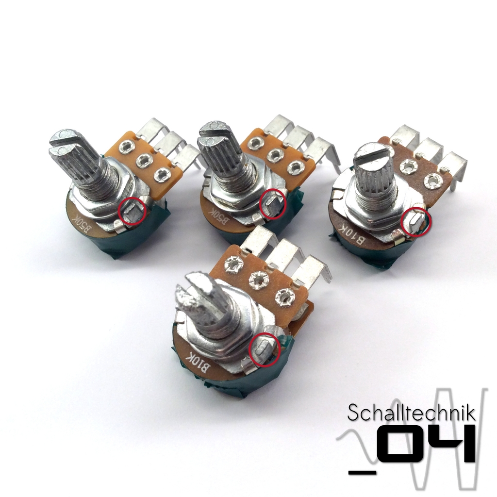 The pots are equipped with small hooks. (as seen on the picture above). They are not needed.
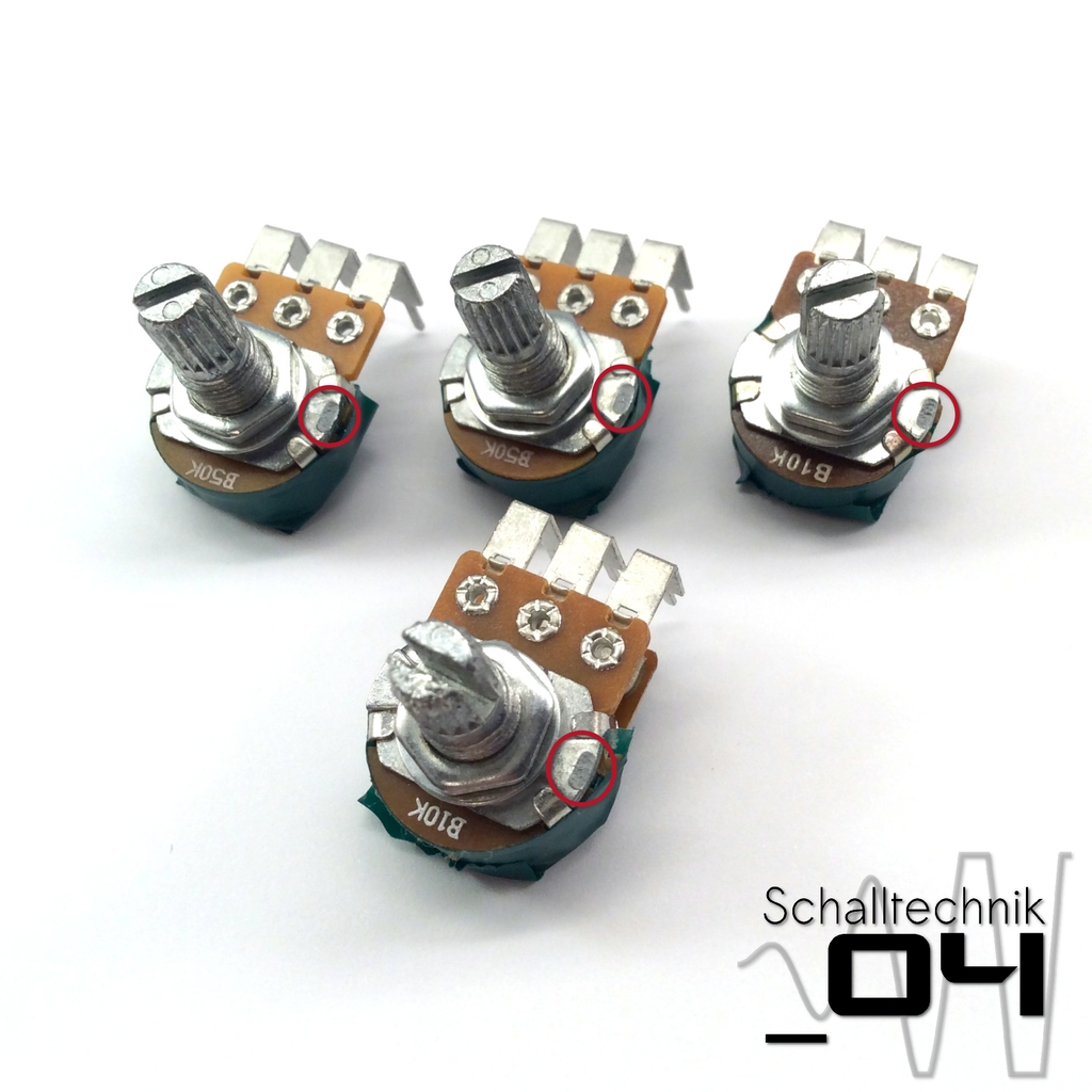 Just break them away with a pair of pliers
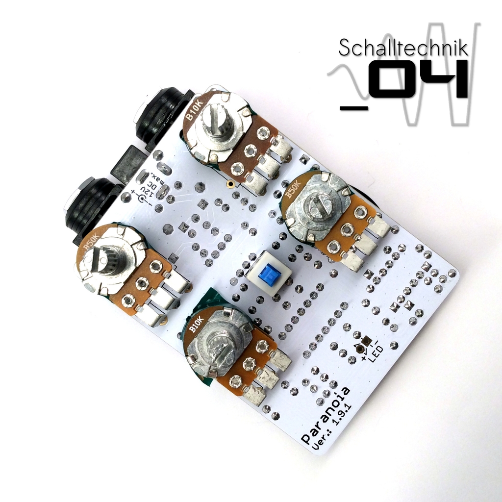 Remove the nuts and washer from the pots. Insert angled pots … don’t solder, yet!
- OUT-VOL: 1x50kB (lin)
- Q: 1x10kB (lin)
- FREQ: 2x10kB (lin)
- CUT/BOOST: 50kB (lin)
 … turn the PCB and solder just one solder joint each.
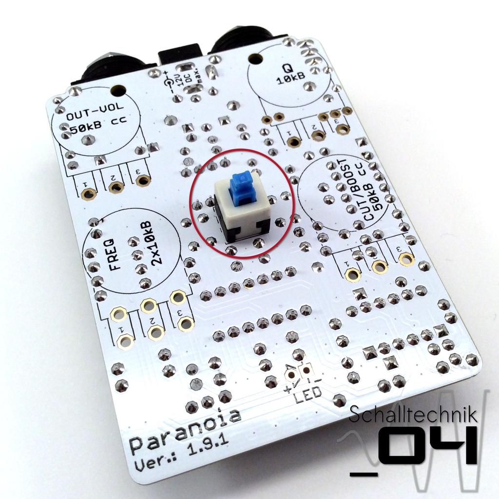
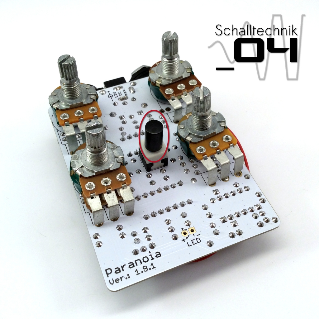 Add the cap of the switch.
 Insert the led. Don’t solder, yet! Align correctly!
- long leg: +
- short leg: –
 Use tape or super glue to fix two washers together (they come with the jacks). Then use super glue to glue the washers to the jacks.