PCB-assembly
Contents
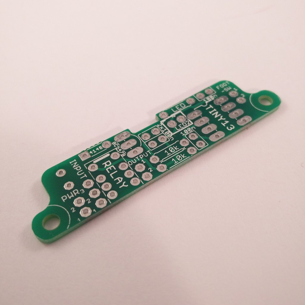
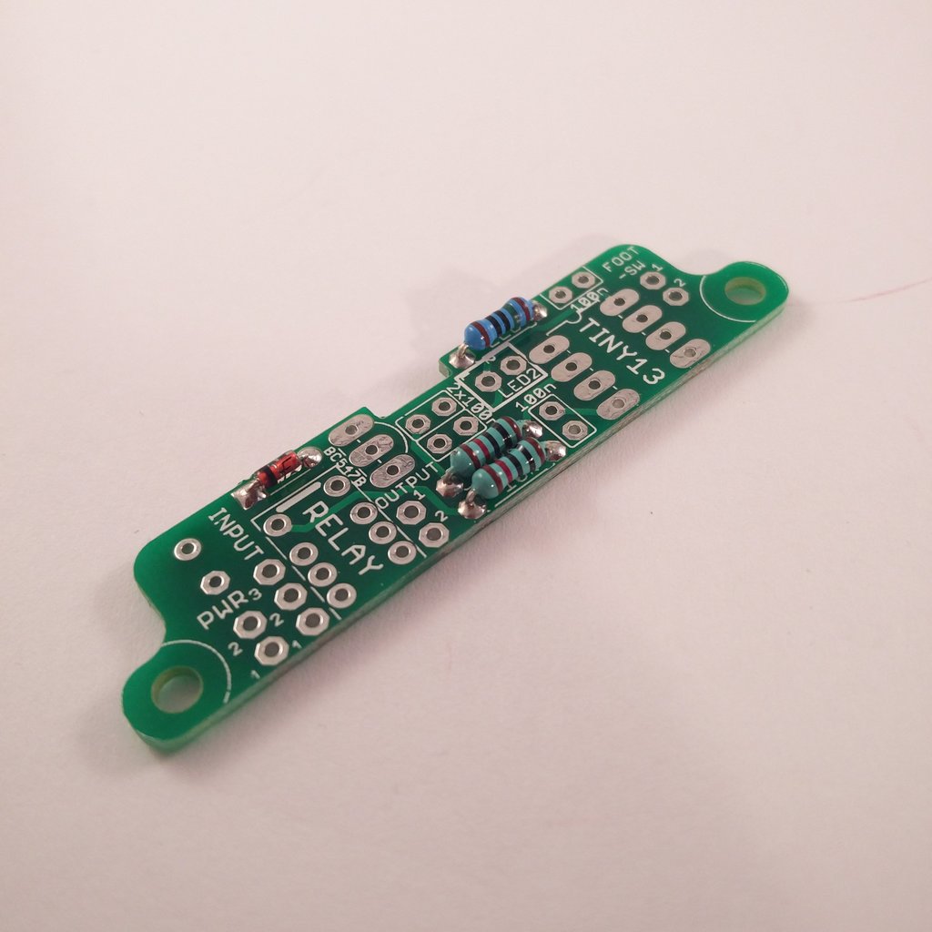
 Insert 1N4148 diode (1x) and solder it. Align correctly!
Sometimes the marking on the silkscreen isn’t very good to see.
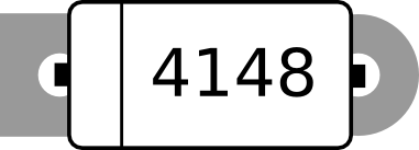
Luckily the land has different shapes. The Cathode (the side with marking) comes in the hole with the square land. (see picture above)
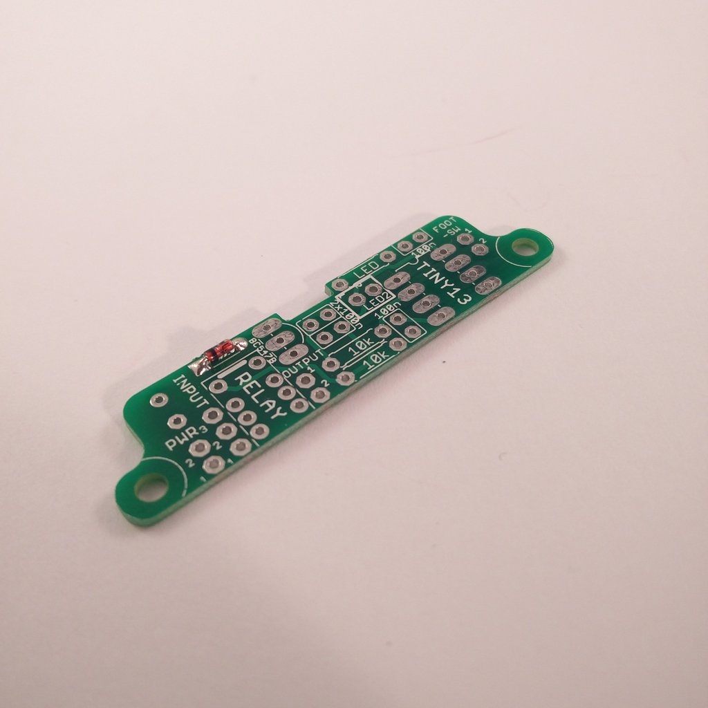
 Insert led resistors (1x) and solder it. (here: 150R)
 Insert 10k resistors (2x) and solder them.
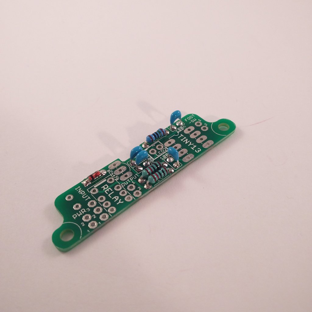 Insert 100nF (104) capacitors (4x) and solder them.
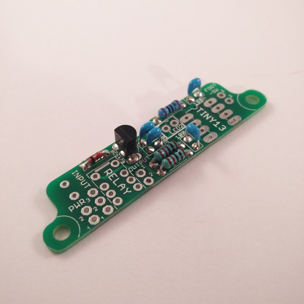 Insert BC547B (1x) and solder it. Align correctly!
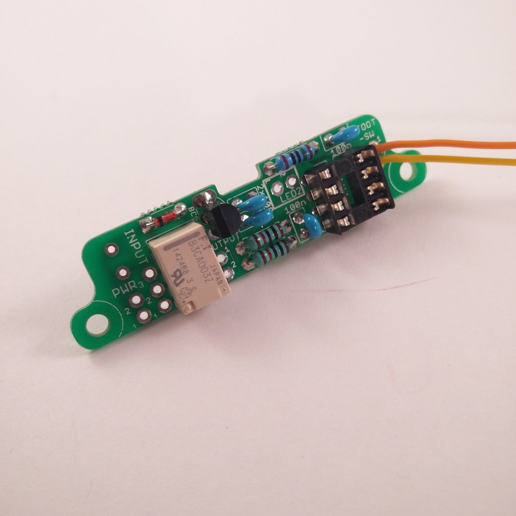
 Insert 8-Pin DIL-Socket (1x) and solder it. Align correctly! Leave no gap between the pcb and the socket. Otherwise its gonna be a tight fit later.
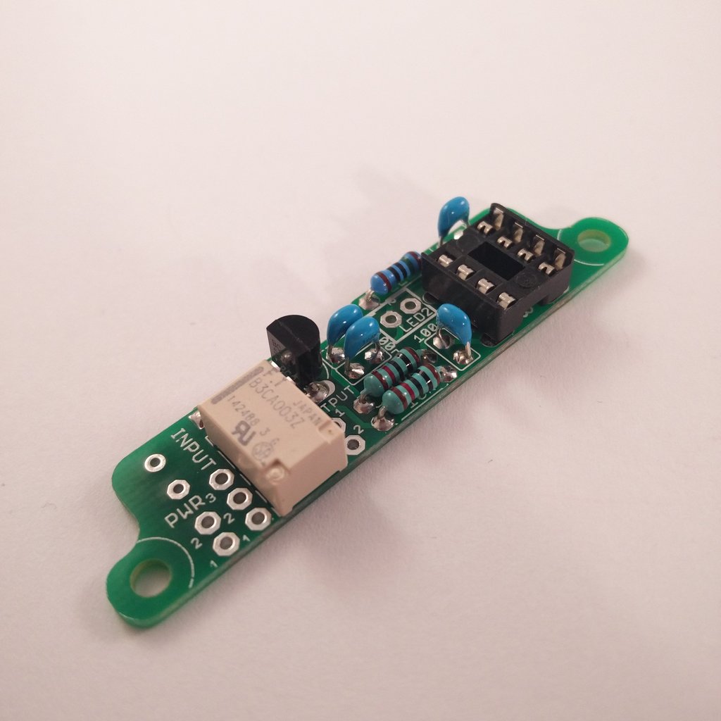 Insert Relay (1x) and solder it.
 Now there’s some wiring to do. I recommend to use the same colours at the same points. Later I’m going to explain the wiring based on the colours I used here.
Foot-SW-Port:
- Pin 1: orange (external/single tap)
- Pin 2: yellow (internal/doppel tap)
If you don’t need or want one of those functions just leave it.
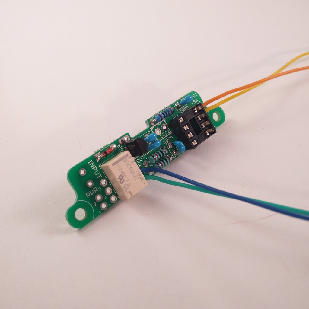
OUTPUT-Port:
- Pin 1 (top): blue
- Pin 2 (bottom): teal
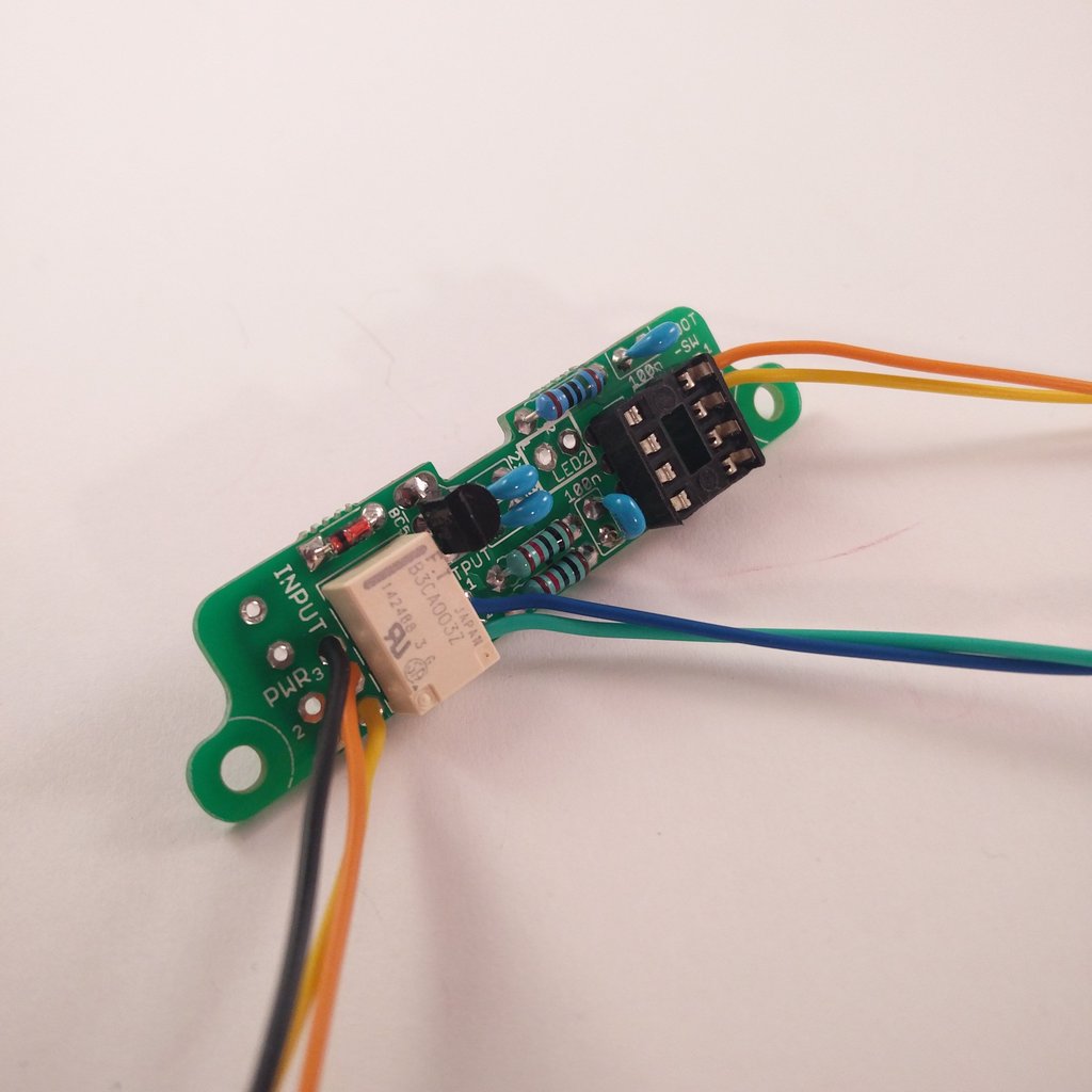
INPUT-Port:
- Pin 1 (top): yellow
- Pin 2 (middle): orange
- Pin 3 (bottom): black
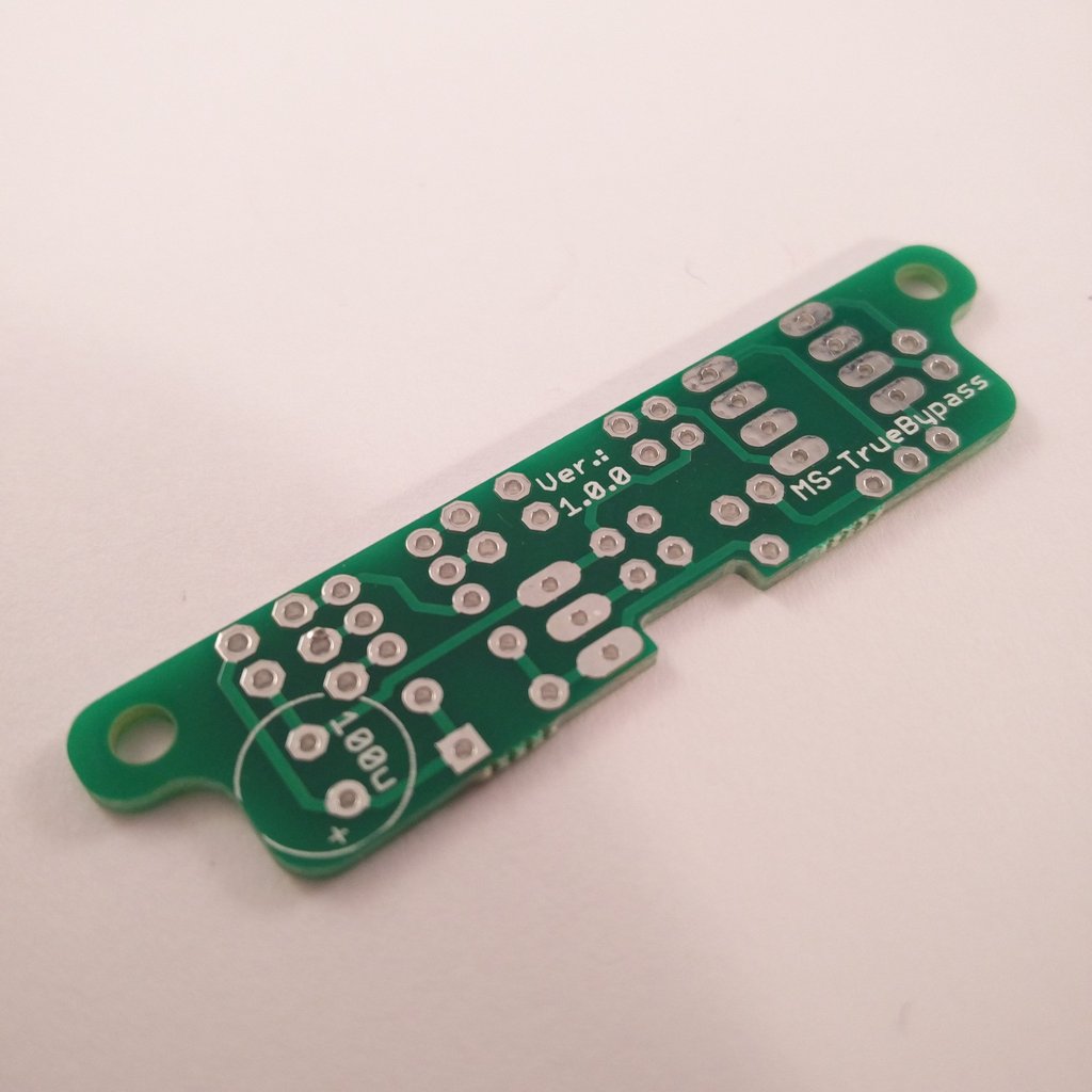
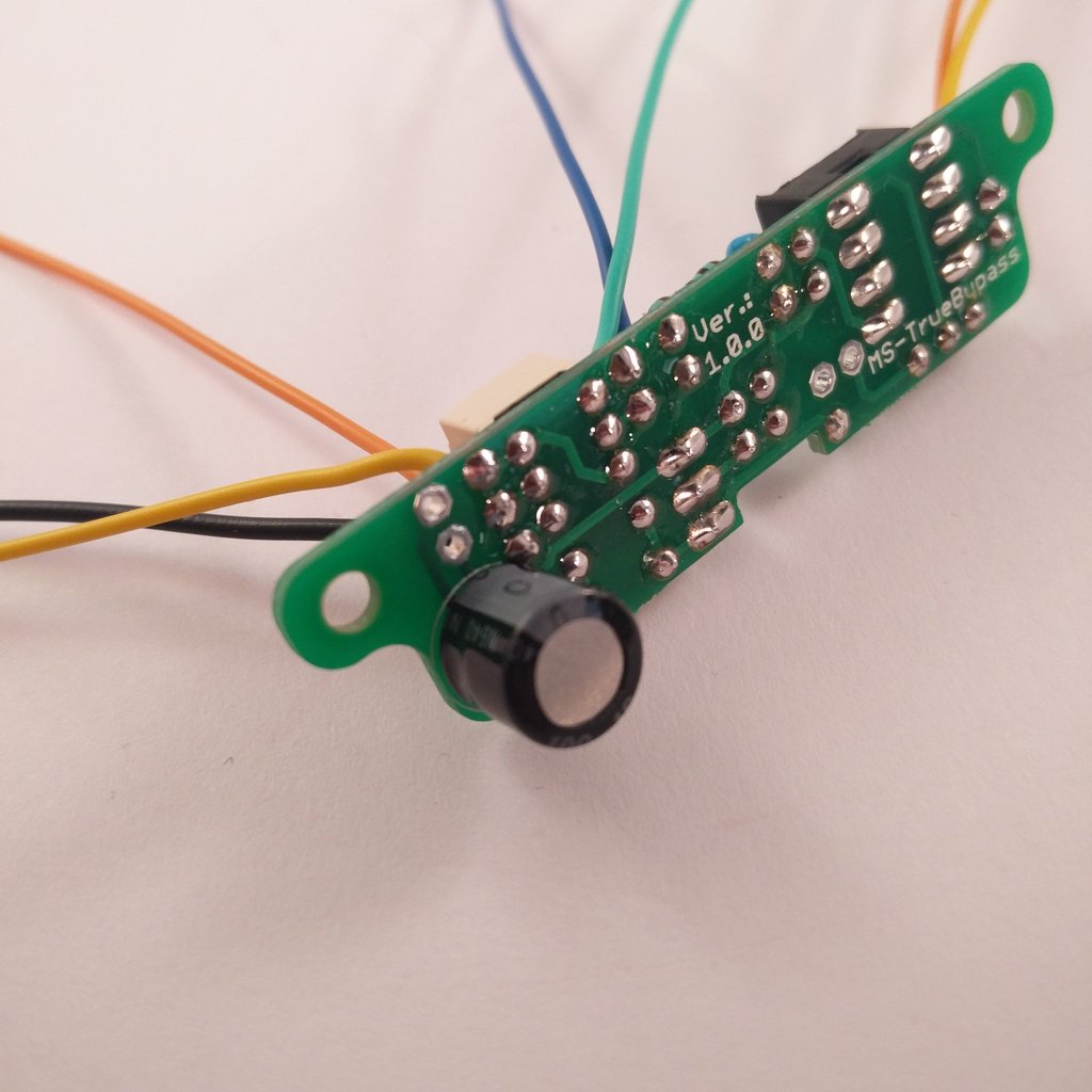 Insert 100µF capacitor (1x) on the backside and solder it. Align correctly!