Modifications 3/3
Contents
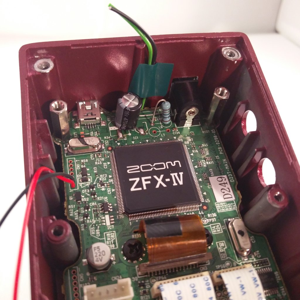 Screw in the two 15mm-M3 bolts
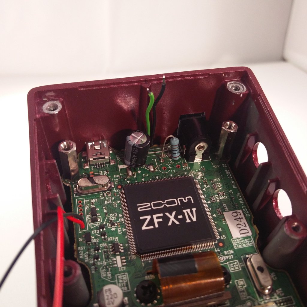 Cut the wires of the led.
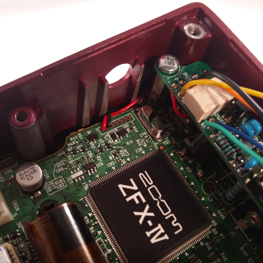
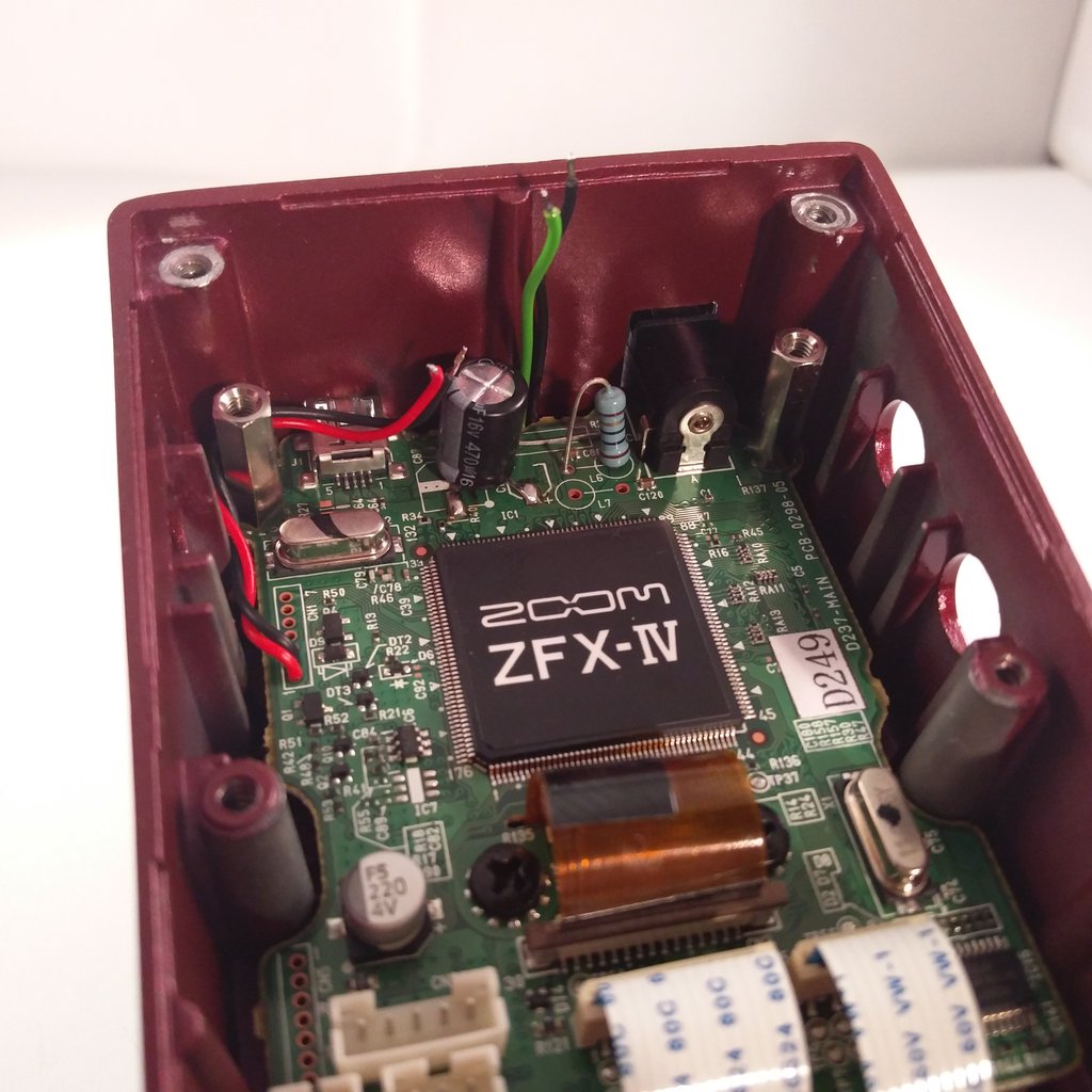 Twist the red and black wire from the mainboard, cut it and lay the wires as shown.
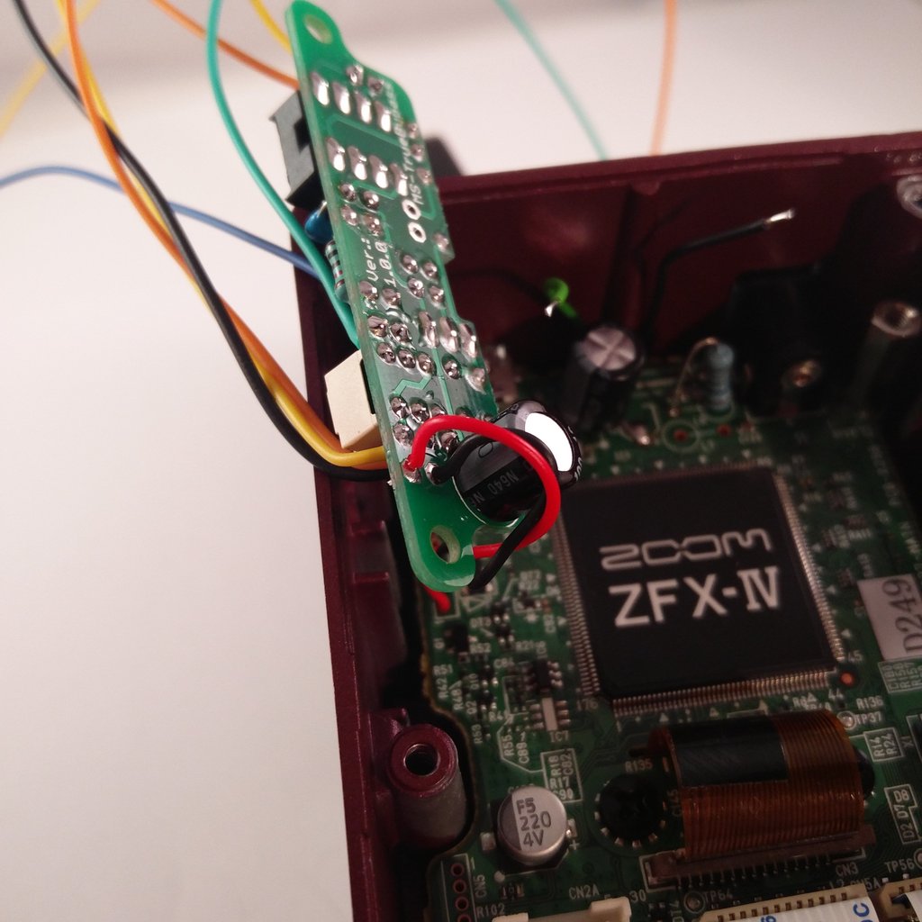 Now solder the black and the red wires from below to the relay board.
Caution!! There’s no polarity protection on the board. So better check twice!
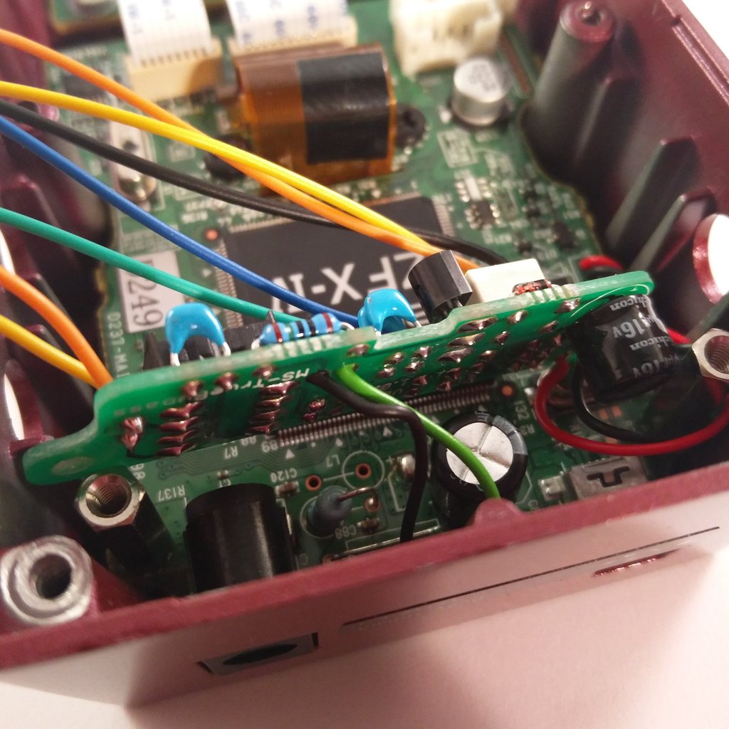 The two cables from the led get also soldered from below to the pcb. Check polarity!
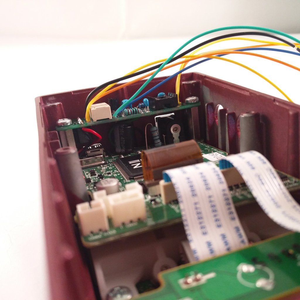
 Now mount the relay-board with two M3 screws to the bolts.
 Here: check that the red and black cable can’t get stuck between the input jack and the enclosure.

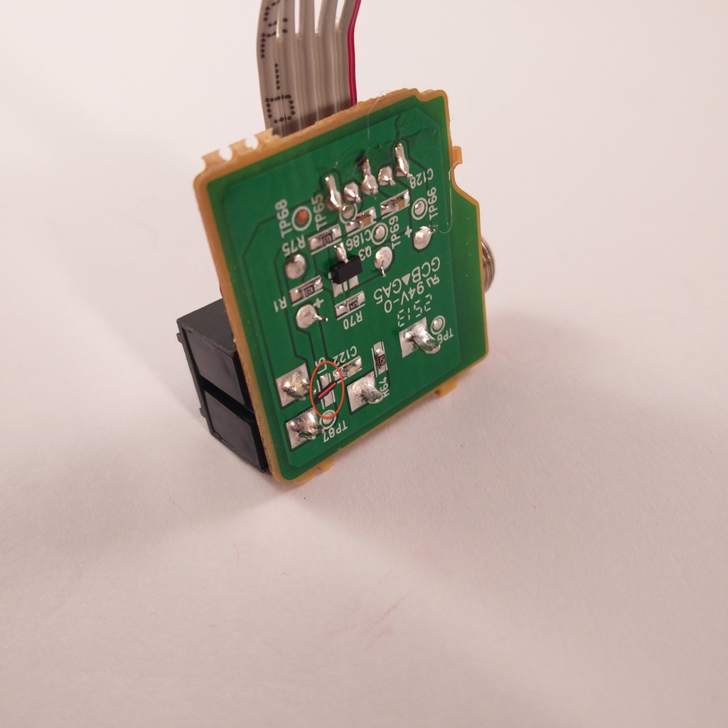 On the pcb with the input jack we need to cut one trace. The place is named “L5” (see picture)
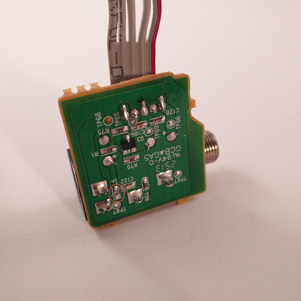 Here you see the the trace already cut. Check with a multimeter if the trace is really cut and also if no connection to GND is present.
Note: GND = TP67
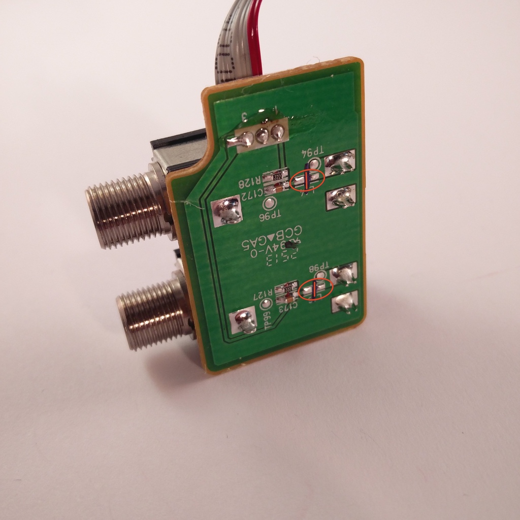 On the pcb with the output jacks we need to cut two traces.
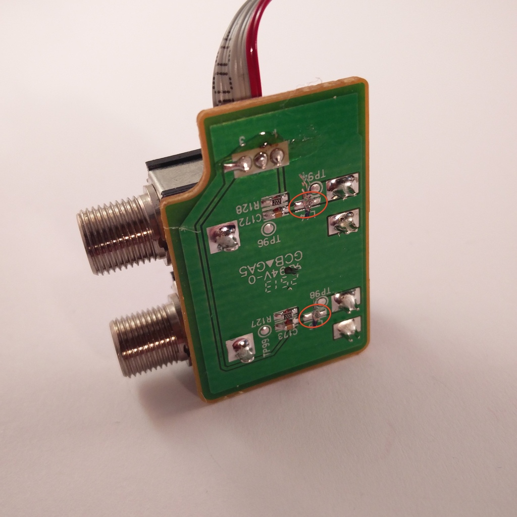 Here you see the the traces already cut. Check with a multimeter if the traces are really cut and also if no connections to GND are present.
Note: GND = TP96