Modifications 1/3
Contents
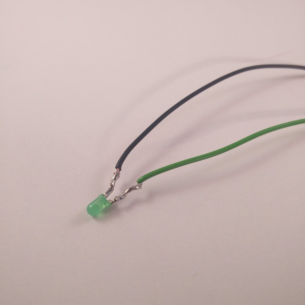 Solder two wires to the led. (long leg/anode – green; short leg/cathode – black)
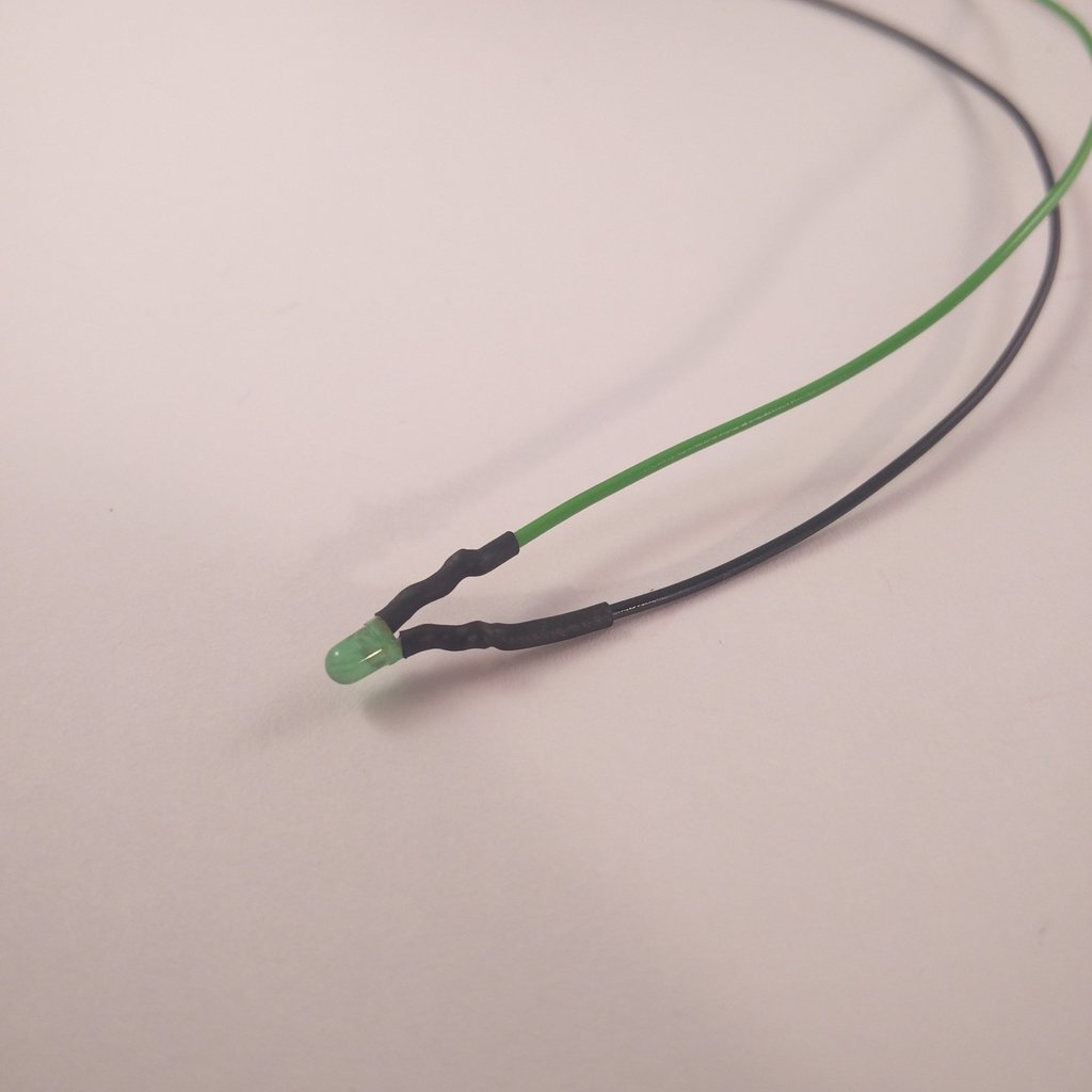 Put some shrink tube over the solder points. It should be completely covered. (no blank metal)
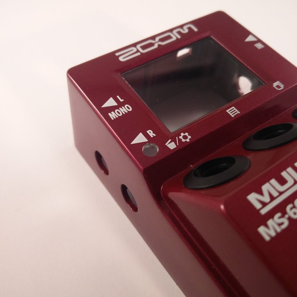 Drill the a 4.2mm hole into the enclosure.
At this point I also recommend to cut the two threads into so the enclosure. I did this step on the next page.
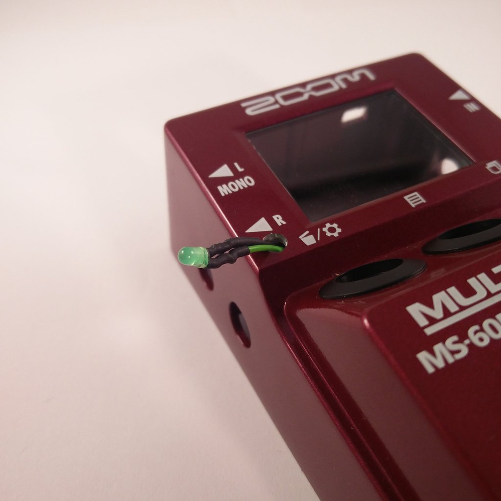 Insert the LED…
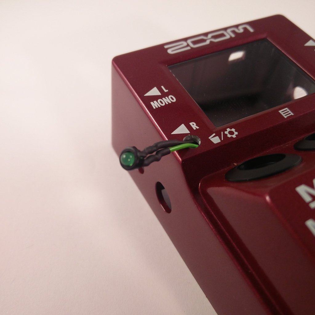 …and put the LED-Clip on it.
 Insert the led with the clip.
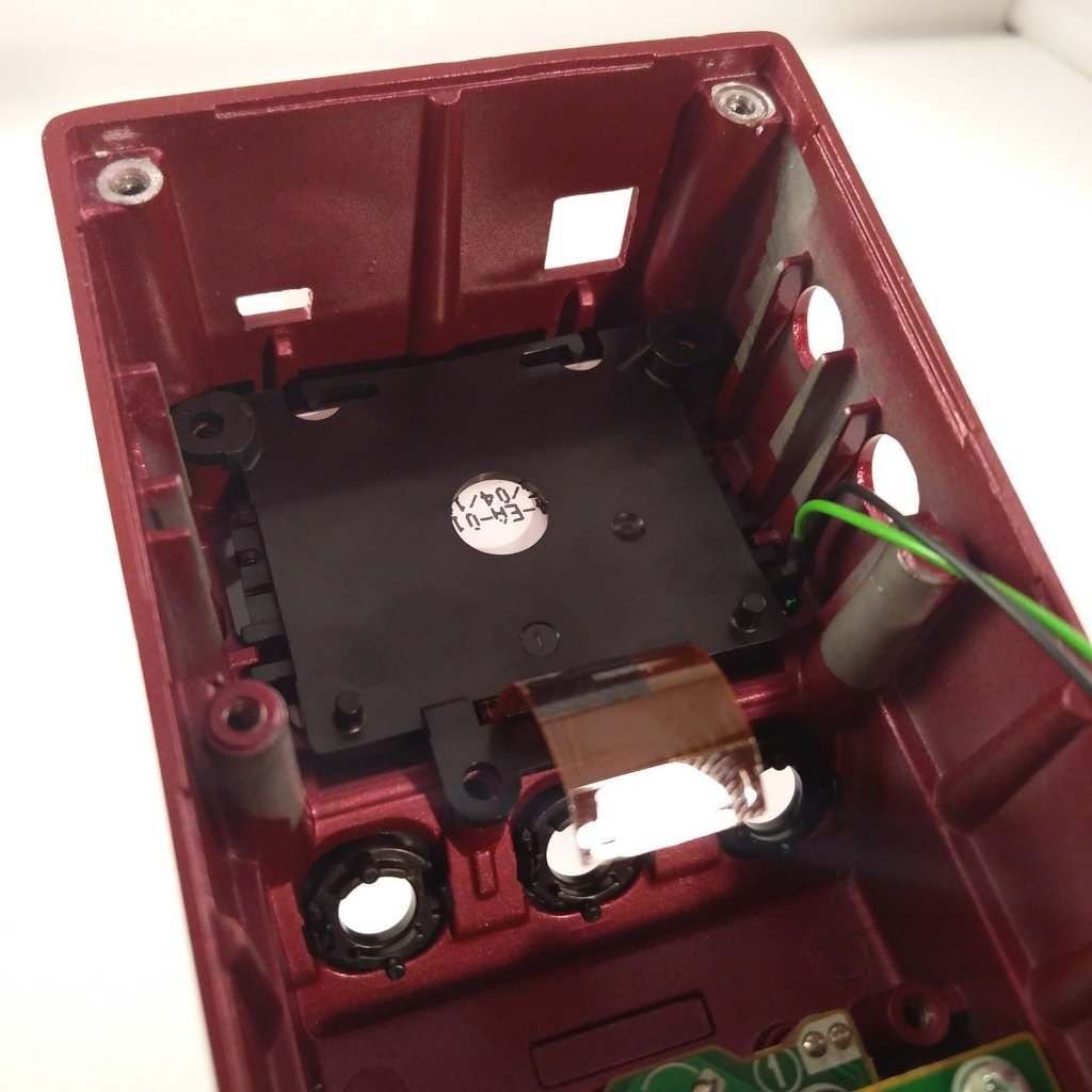 Reinsert the display. Remove all the dust and partials between the display and the glass.
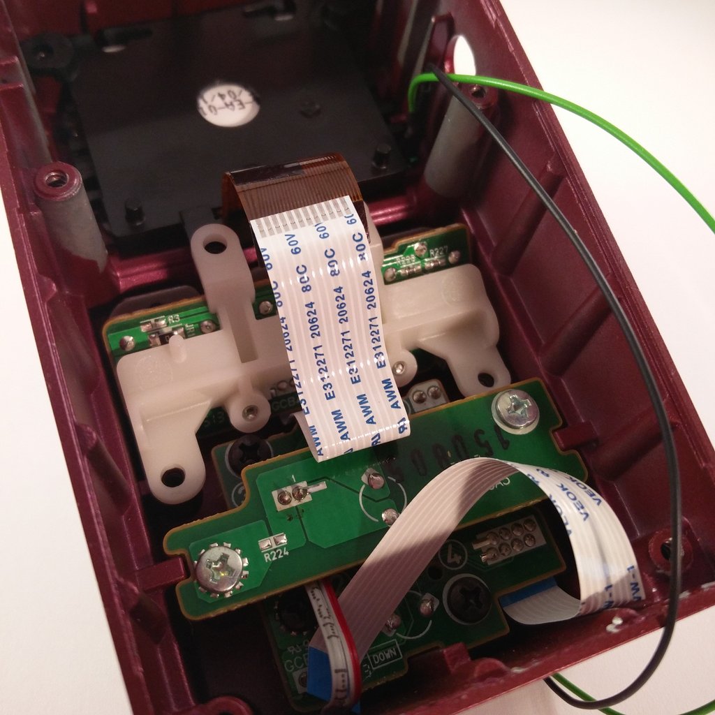 Re-insert the pcb with the rotary encoders.
 And don’t forget the two screws!
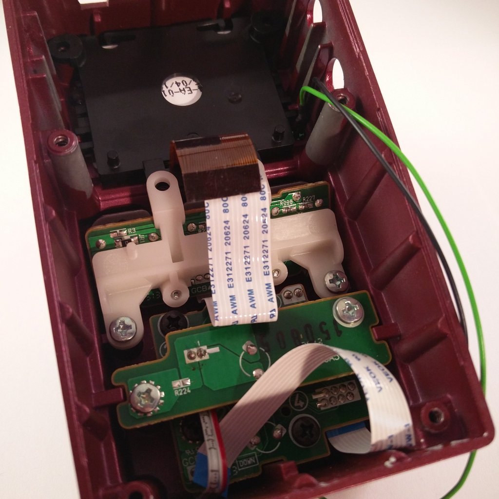
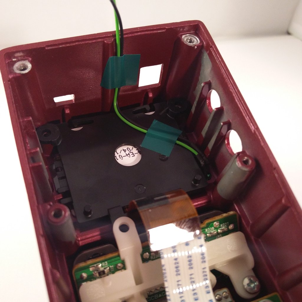 Bend the legs of the led as show in the picture and fix it with some tape.
 We’re gonna need some power for the relay-board. So we use this unused port Pin 1 (bottom) = 3,3V; Pin 2 (once above) = GND
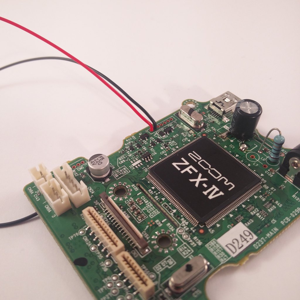 The pcb is a multi-layer board and the ground plane is huge. So don’t be surprised if you need a little bit longer for a good solder joint.