Reassembly 1/2
Contents
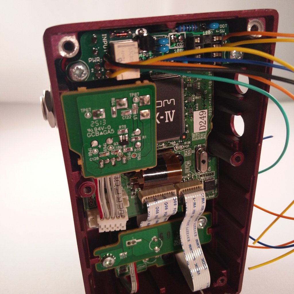 Re-mount the first pcb… (Keep the red and black wires in mind while tightening the jack!)
 …and plug the ribbon cable back into the main-board.
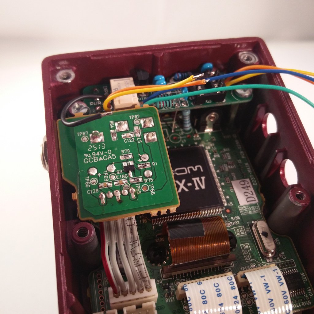 Cut the black wire from the INPUT-Port…
 …and solder it to the pcb as shown in the picture. Afterwards do the same with the yellow cable from the INPUT-Port.
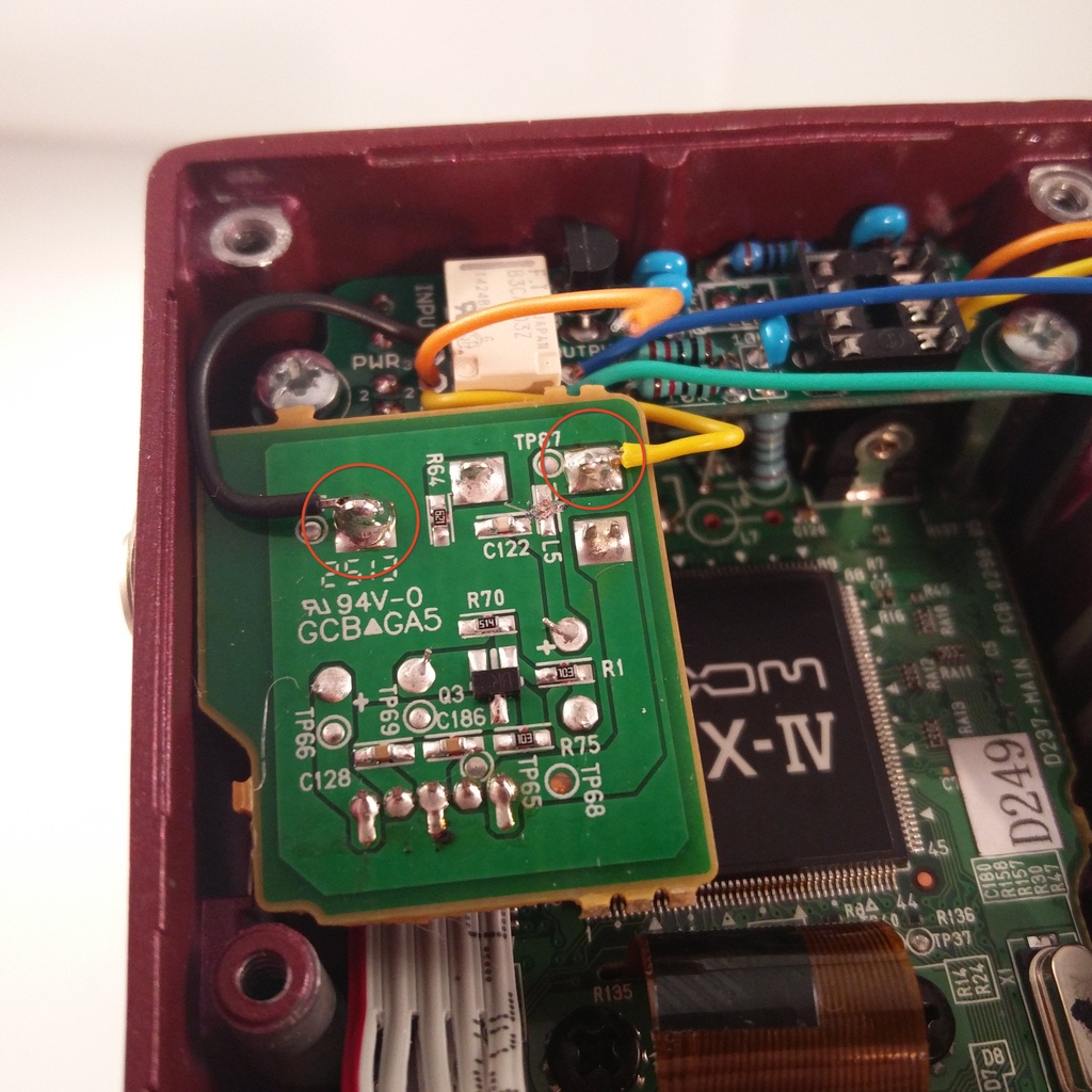
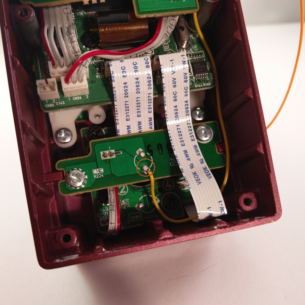
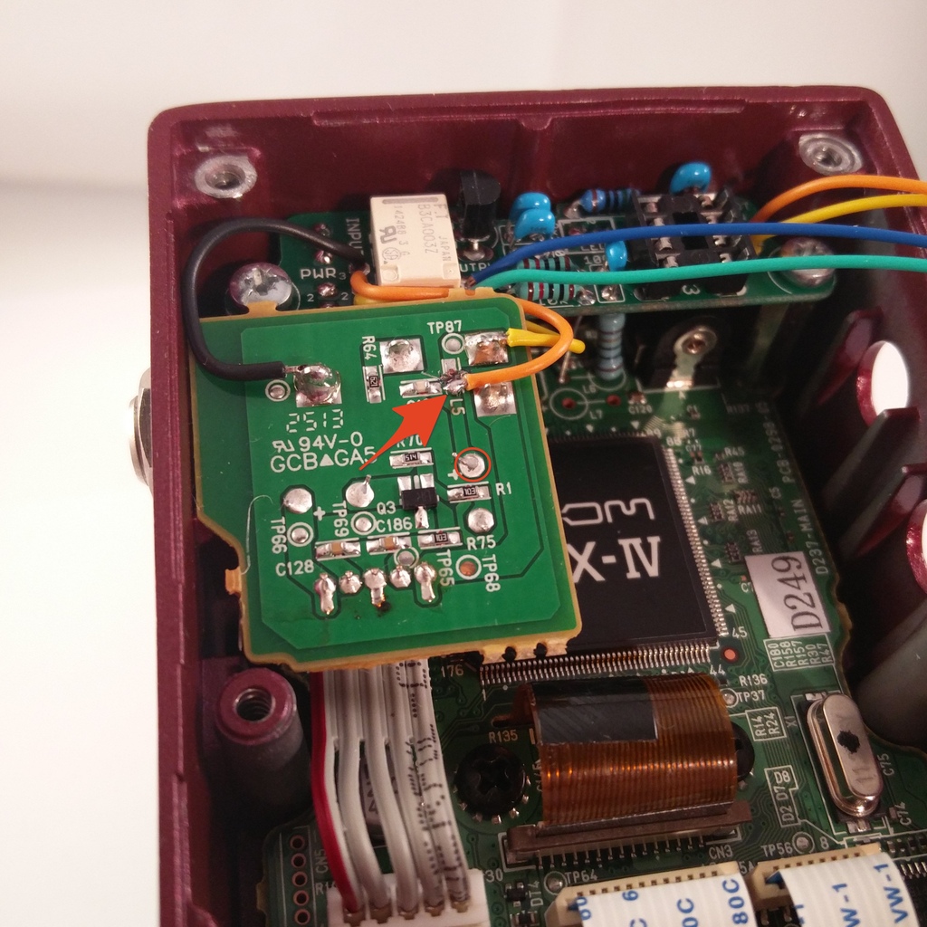 On the picture you see the orange Cable from the INPUT-Port soldered to the lower pad where we cut the traces. This pad is very small. Therefore it’s recommended to solder it the solder joint marked with a circle instead.
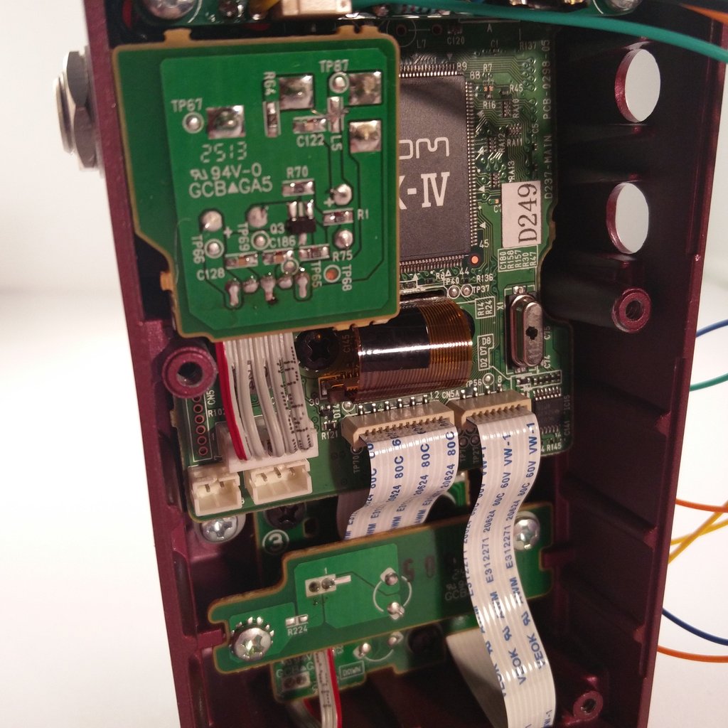
 Remount the second pcb…
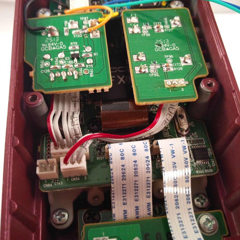 …and plug the ribbon cable back into the main-board.
 Now cut the teal-coloured cable from the OUTPUT-Port…
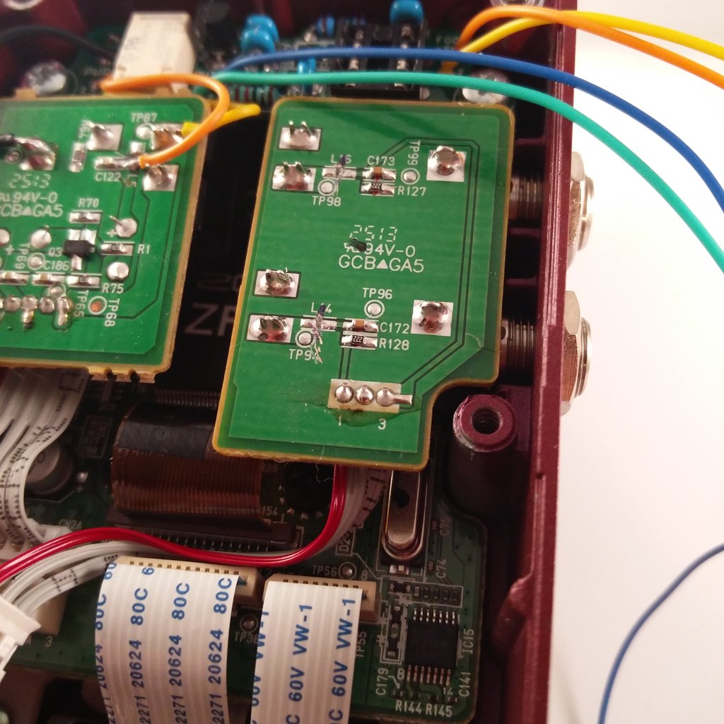
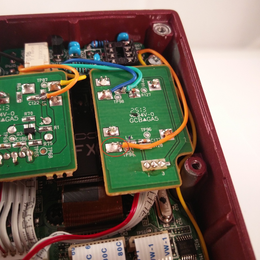
 …and solder it to Point “3” (marked with a circle). On the picture you see it was done differently, but – here again – the other pad is tiny.
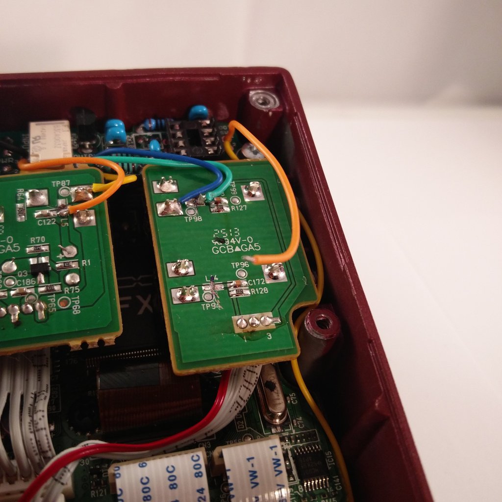
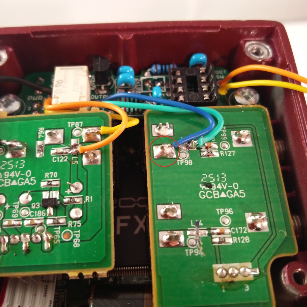 Solder the blue cable from OUTPUT-Port to the pcb, as shown on the picture.
 The yellow cable from the FOOT-SW-Port used for the double tap to bypass function.
 Solder it to the pcb as shown.
 The orange cable from the FOOT-SW-Port gets cut…
 …soldered to the pcb as shown in the picture.