Assembly Preparations
Contents
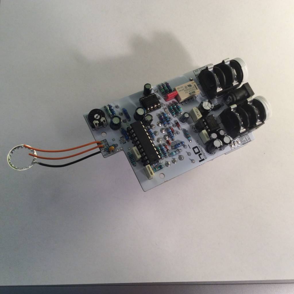
Now we take the tooth washer which comes with the footswitch and solder a wire to it.
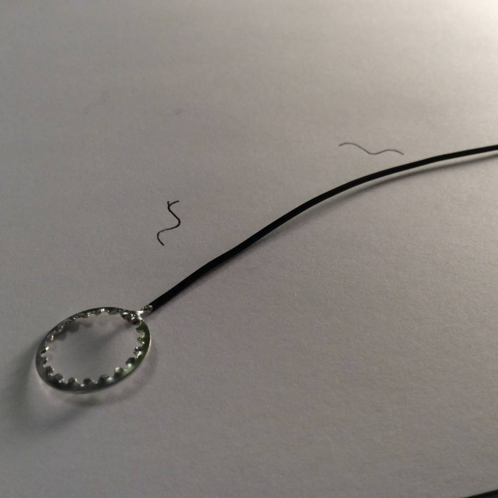
We’ll use the tooth washer later to ground the enclosure.
About shielding:
If we ground the enclosure it will act like a shild. Ungrounded the shielding effect is much smaller.
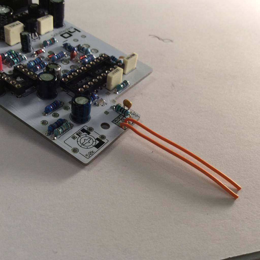 Solder wires to the “ON/OFF”-Port.

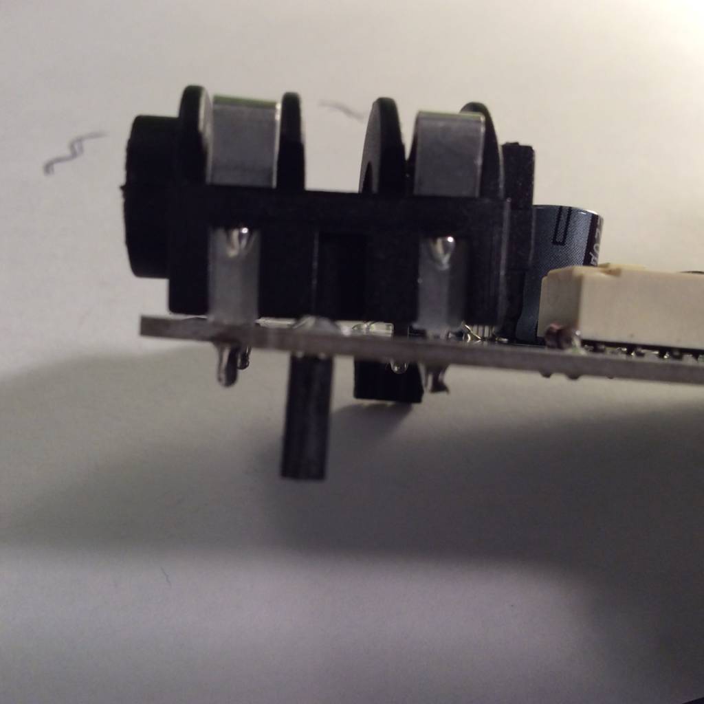
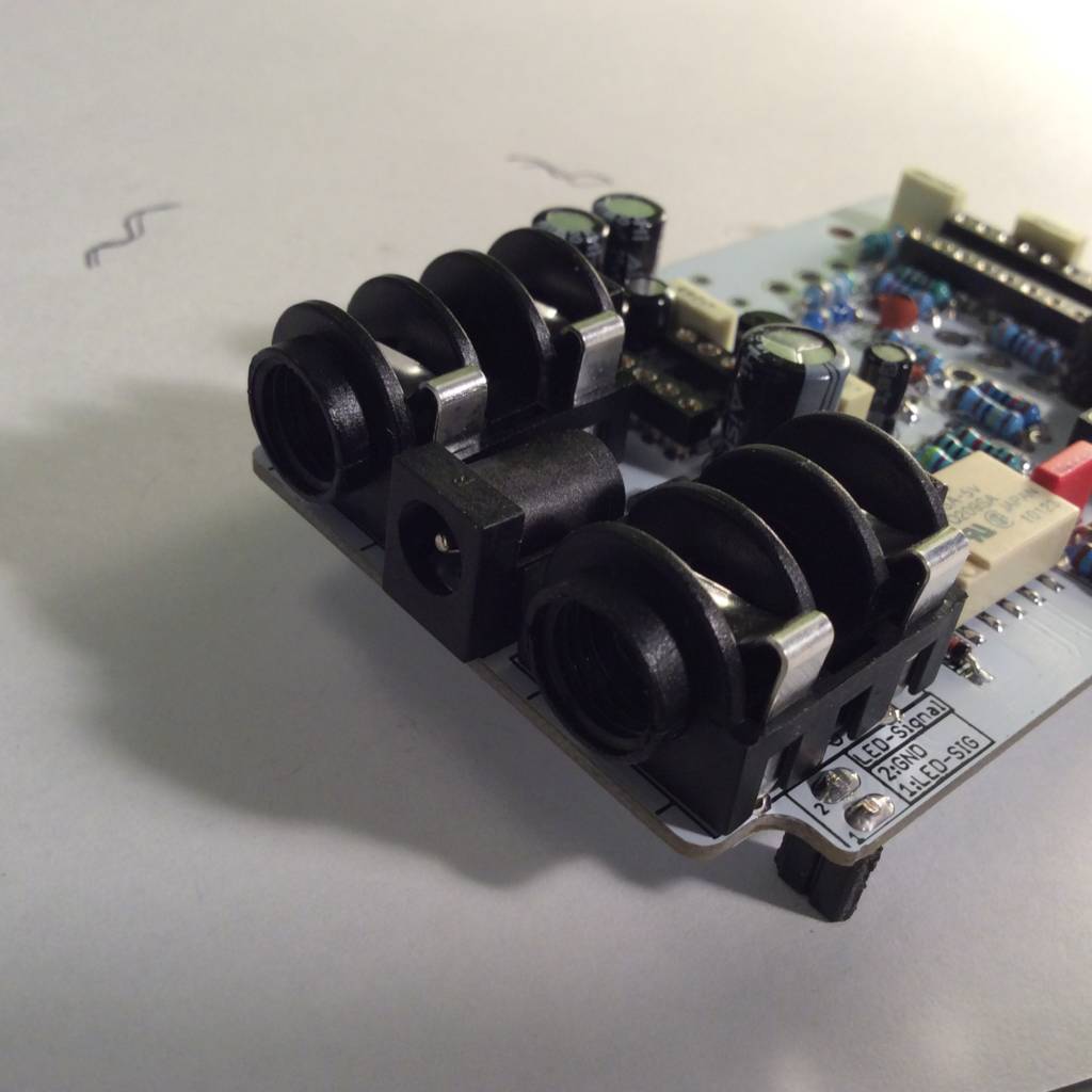
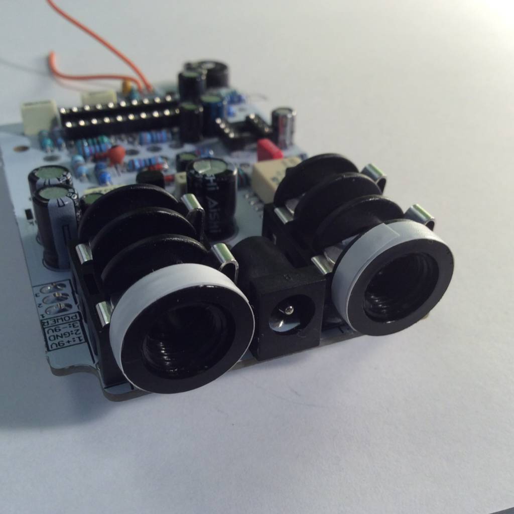
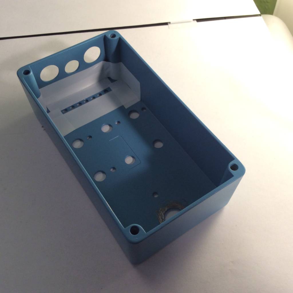
The 125B/1590N1-enclosures aren’t rectangular, thus we need to mount the input- and outputjacks with a small angle. I use a piece of wire, which I put under the jacks (see in the pictures). Then I solder them.
Insert the dc-jack…

and solder it.

Note: If you like, you can cautiously clean the areas arround the jacks again with PCB-cleaner.
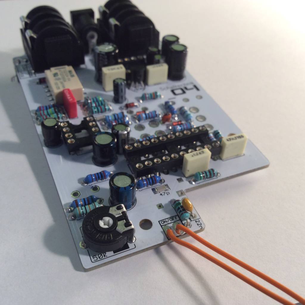
Insert the trim-pot and solder it.
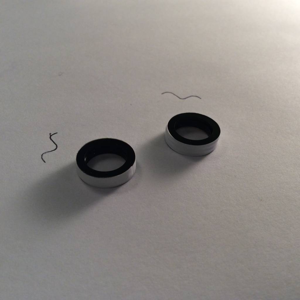
Use tape to fix three washers together. (they come with the jacks)
Note: In the meantime I use only two washers. The handling is overall easier.
Then use hot glue or super glue to glue the washers to the jacks.
If you use hot glue, make sure not to apply to much glue.

Put two layers of tape on the pots to ensure the housing can’t touch the soldered points.
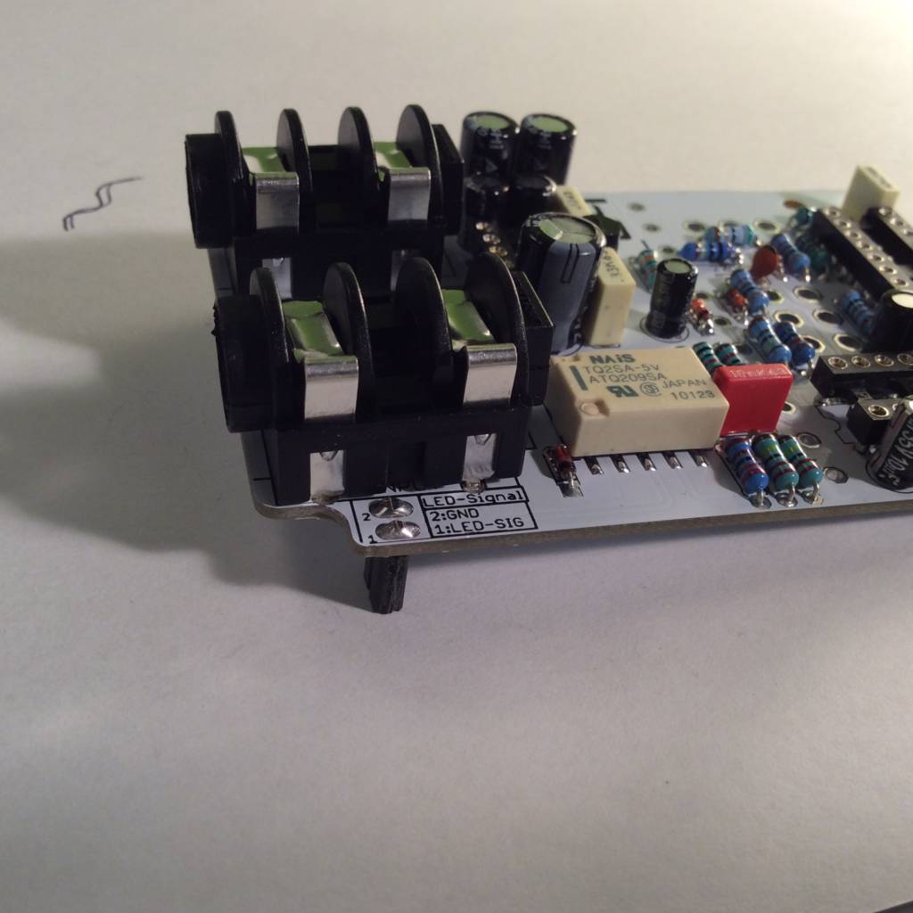
Put some insulating tape around the area where LED-Indicator-Board will be.
This step is highly recommended!
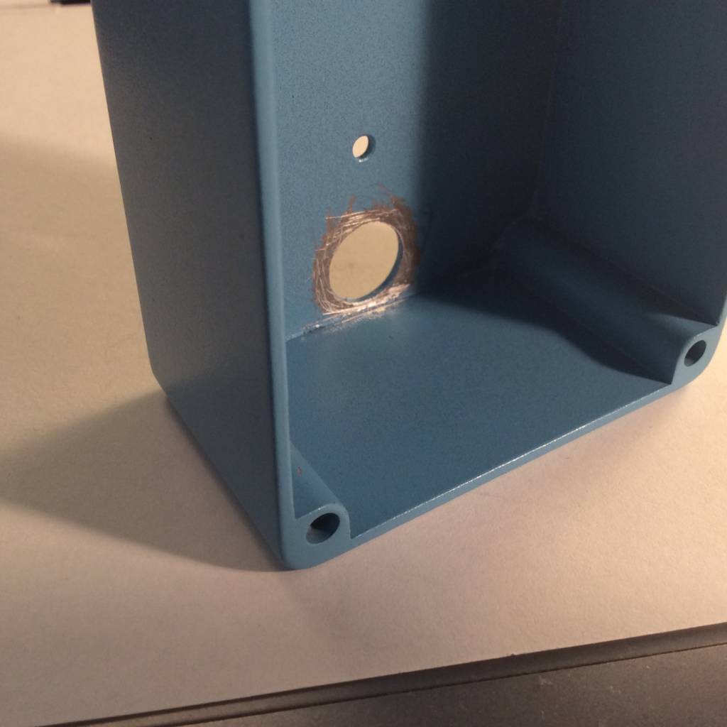 Scratch off some coating arround the footswitch-hole to ensure an electrical connection between the enclosure and the theeth washer.
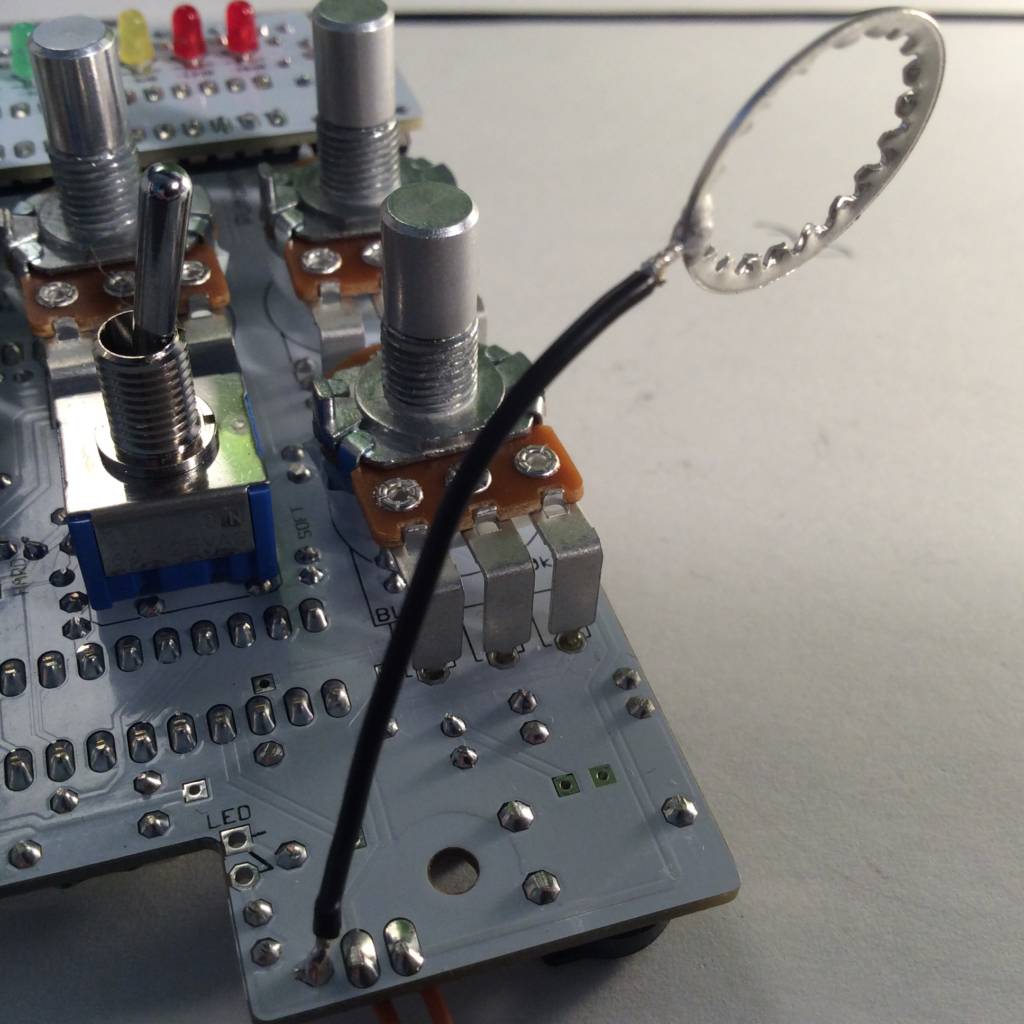
Solder the theeth washer wire to the pcb. I used the solder joint of the LED-resistor [GND] (next to the “ON/OFF”-Port). Newer PCB-Versions (≥ Ver.:1.2.0) got a dedicated pad (named GND) to do so.
(Please ignor the already mounted pots and switches) 😉
At the end you can insert the ics in their socket. Align correctly!