PCB-assembly 1/6
Contents
HALT! STOP!
Are you starting to assemble a kit bought not directly from schalltechnik_04.de? If yes, check every part again the list of parts.
Really! E.V.E.R.Y. Part!
If anything is wrong -> contact your seller!
If you’re not certain, if it is the correct part -> contact us.
It’s 10 mins invested, that will later safe you headaches.
HALT! STOP!
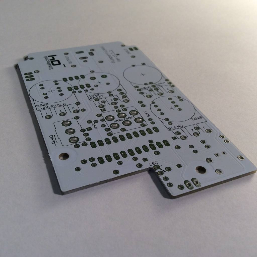
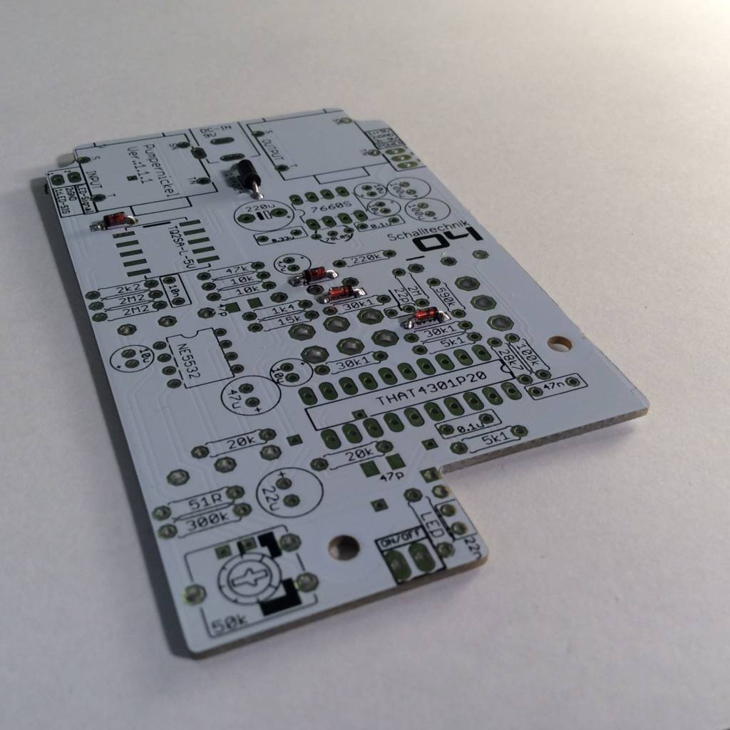
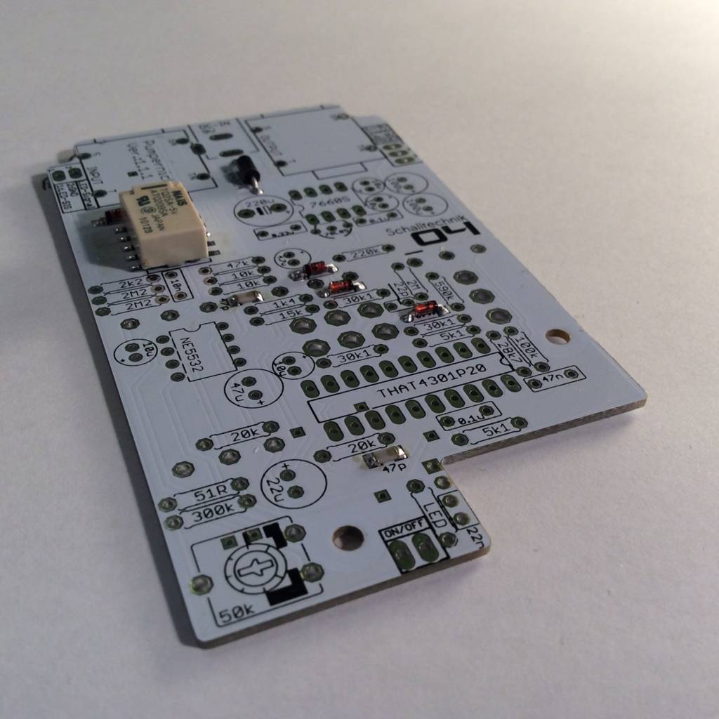
With that out of the way, let’s start building. 🙂 The Pumpernickel kit consists of two pcbs. The main-board and the LED-Indicator-board. It gets delivered as one pcb.

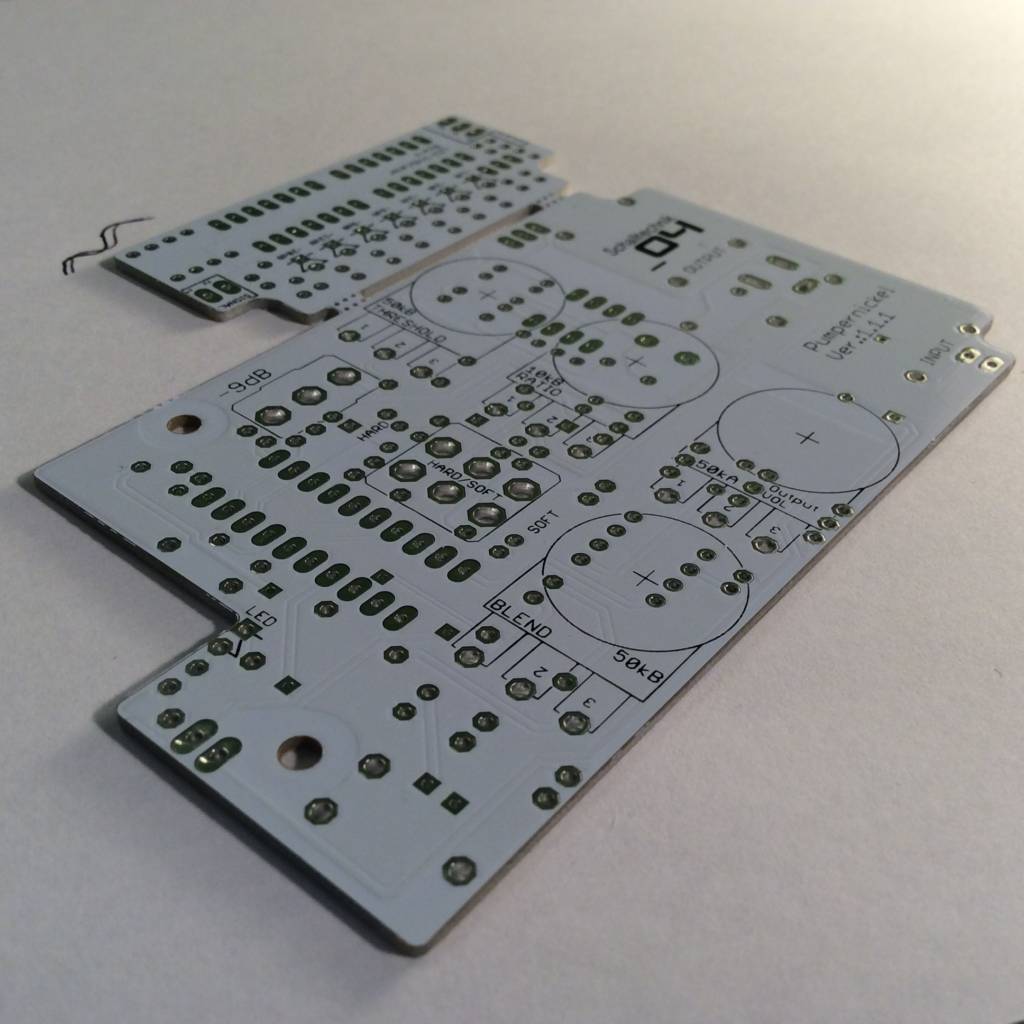
First we got to part the pcbs. The pcb has predetermined breaking points. If you want to play save, you can part the pcbs with a saw via hand. After that grind the breaking points a little bit.
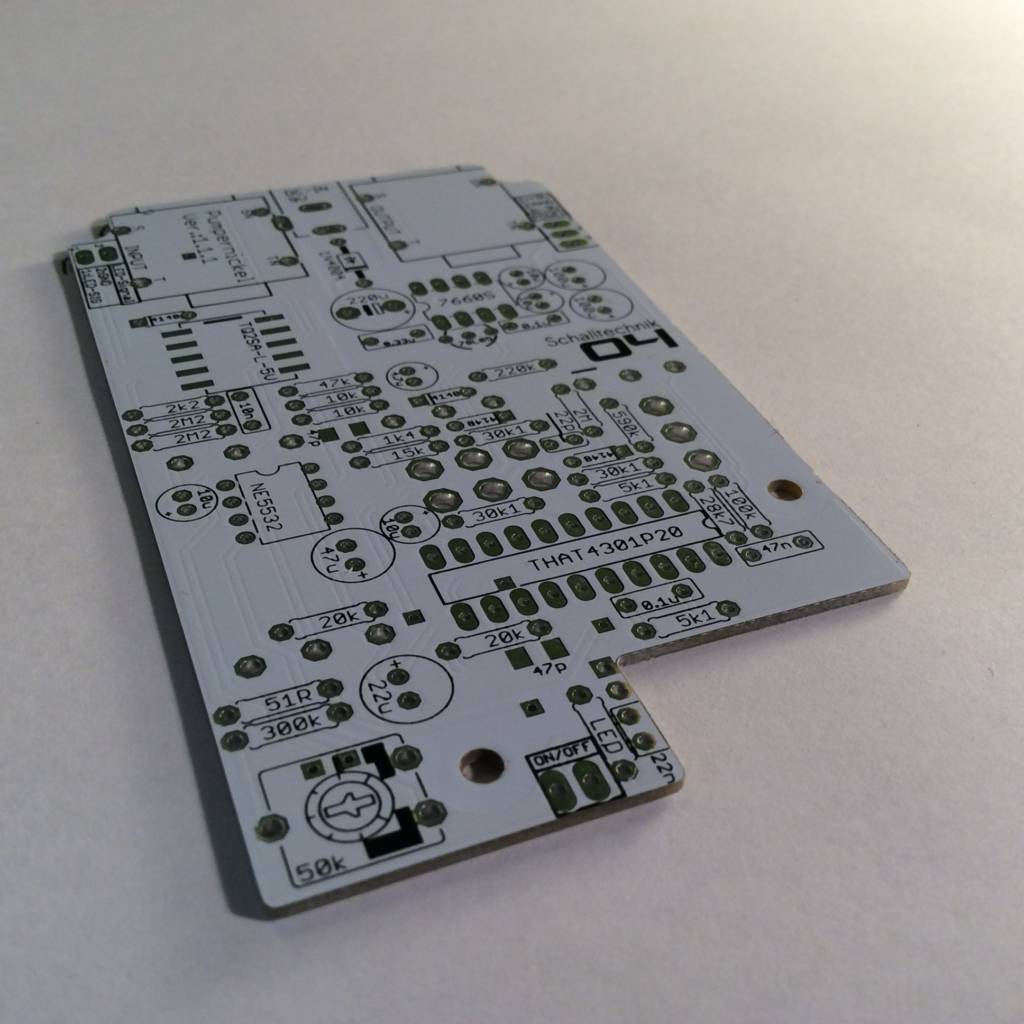
Ready to solder…
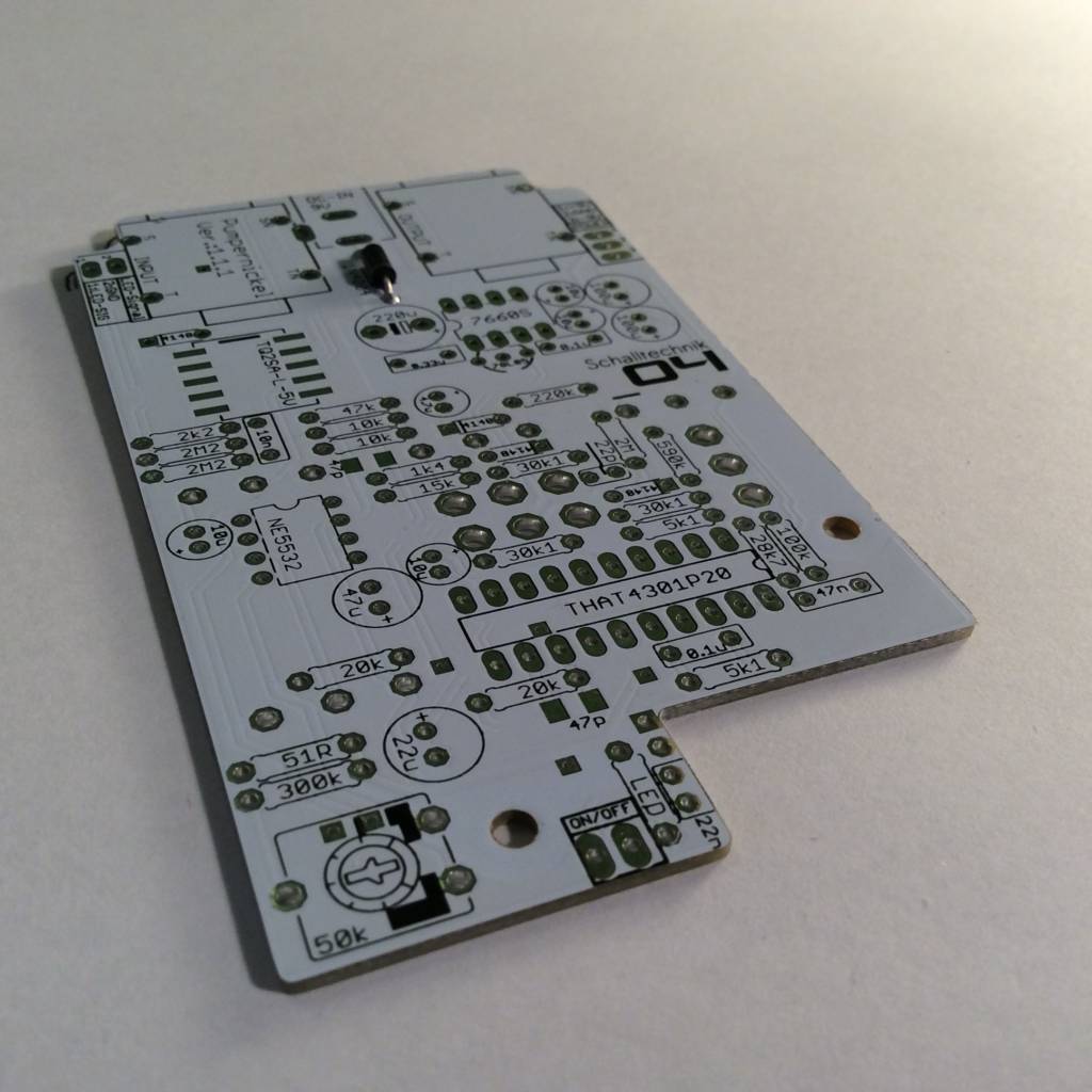
Insert 1N4003 diode (1x) and solder it. Align correctly!
Insert 1N4148 diodes (4x) and solder them. Align correctly!
Sometimes the marking on the silkscreen isn’t very good to spot.
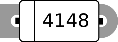
Luckily the land has different shapes. The Cathode (the side with marking) comes in the hole with the square land. (see picture above)
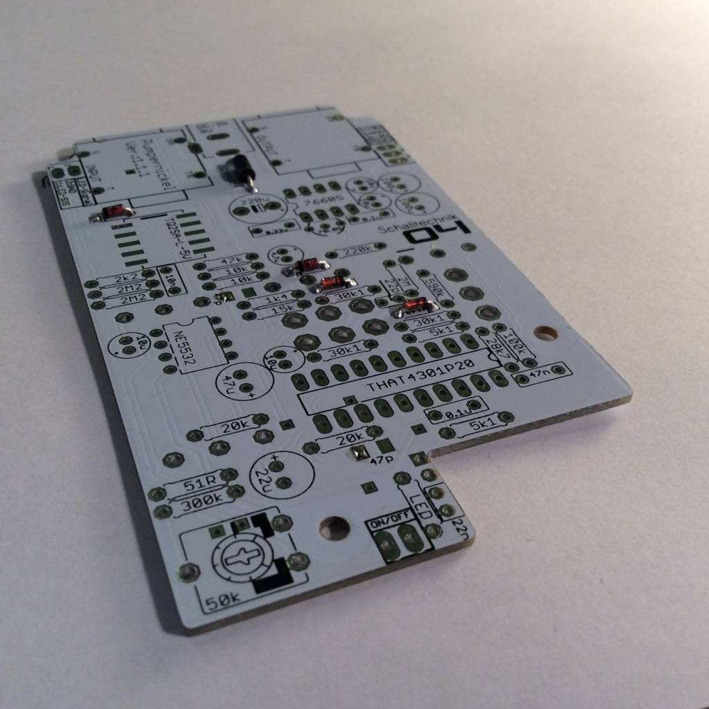
On the picture above you see the first step for soldering the 47pF SMD-capacitors. One pad per capacitor gets coated with solder. Now you take a capacitor with tweezers and place and fix it on the corresponding place. Heat up the pad (you coated before) and pin (of the capacitor) to get a joint.
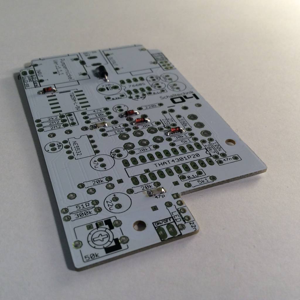
The other pins of the capacitor can be soldered normally (heat up the pad, put solder to it, done).
Relay: Now we do the same procedure as with the SMD capacitors: Coat one pad on the pcb and take the relay. Put it in the right place und solder the coated pad to the relay pin. Afterwards solder the other 9 pins/pads together.
NOTE: Newer versions (≥ 1.2.0) of the pcb use a through hole Relay. It’s easier to solder.
Align correctly!